ford fusion 2011 owners manual

This manual provides essential guidance for operating and maintaining your 2011 Ford Fusion‚ ensuring a safe and enjoyable driving experience․
It details features‚ controls‚ and important safety information‚ alongside scheduled maintenance procedures․ Understanding this manual will help you maximize your vehicle’s performance and longevity‚ addressing potential issues like braking anomalies or engine concerns reported by other Ford owners in 2024 and 2025․

Overview of the Vehicle

The 2011 Ford Fusion represents a blend of style‚ comfort‚ and efficiency within the mid-size sedan segment․ This vehicle offers a range of powertrains‚ including a standard 2․5-liter four-cylinder engine and optional 3․5-liter V6‚ catering to diverse driving preferences․ Available in various trims – from the base to the luxurious Fusion SEL – it provides features like SYNC infotainment‚ advanced safety systems‚ and a spacious interior designed for passenger comfort․

As a Ford vehicle owner‚ you’ll find similarities in reported issues across models‚ such as concerns regarding braking systems (as seen in C-Max/B-Max reports) and engine performance (Transit and Puma examples)․ While specific to the Fusion‚ understanding Ford’s broader quality trends is beneficial․ Regular maintenance‚ as outlined in this manual‚ is crucial‚ especially regarding timing components like belts or chains (Puma and Transit Custom cases)‚ and monitoring systems like TPMS (Fiesta reports)․ This overview sets the stage for a comprehensive understanding of your 2011 Fusion‚ empowering you to maintain its optimal condition․

Purpose of the Owner’s Manual

This Owner’s Manual serves as your primary resource for understanding and operating your 2011 Ford Fusion safely and effectively․ It’s designed to familiarize you with the vehicle’s features‚ controls‚ and capabilities‚ ensuring a positive ownership experience․ Beyond basic operation‚ this manual details crucial maintenance schedules‚ helping you preserve the Fusion’s reliability and value over time․

Recent reports concerning various Ford models – from the C-Max’s braking issues to the Puma’s engine concerns and the Transit’s mechanical failures – highlight the importance of proactive vehicle care․ This manual provides the knowledge to address potential problems‚ interpret warning signals‚ and perform routine checks․ It’s a guide to understanding your vehicle’s systems‚ similar to needing to know about timing belts (Transit Custom) or tire pressure monitoring (Fiesta)․ By diligently following the guidance within‚ you’ll be equipped to handle most situations and maintain your Fusion in peak condition‚ preventing issues before they escalate․

Understanding Your Vehicle

Familiarize yourself with the 2011 Fusion’s components‚ from dashboard indicators to the instrument cluster‚ ensuring safe operation․ Recent Ford owner experiences emphasize diligent system monitoring and prompt attention to alerts․

Dashboard Symbols and Indicators

The 2011 Ford Fusion’s dashboard utilizes a series of symbols and indicators to communicate vital information about your vehicle’s status․ Understanding these is crucial for safe and informed driving․ Illumination of a symbol doesn’t always indicate a severe problem‚ but requires investigation․

Warning Lights: These indicate potentially serious issues demanding immediate attention․ Examples include the check engine light (often related to engine or emission control problems‚ as seen in recent Ford Transit reports)‚ oil pressure warning‚ and battery warning․ Ignoring these can lead to significant damage․

Indicator Lights: These lights signal that a system is actively engaged or functioning․ Examples include turn signal indicators‚ high beam indicator‚ and cruise control indicator․

Information Displays: Some symbols are part of the information display‚ providing details like outside temperature‚ fuel economy‚ and trip information․ Pay attention to tire pressure monitoring system (TPMS) alerts‚ as reported by Fiesta owners‚ as maintaining correct tire pressure is vital for safety and fuel efficiency․ Consult the full owner’s manual for a comprehensive explanation of each symbol and recommended actions․

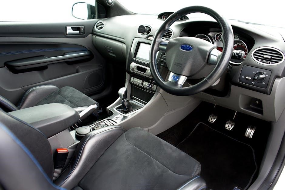
Instrument Cluster Details

The 2011 Ford Fusion’s instrument cluster is centrally located for easy driver visibility‚ providing key vehicle information․ The primary components include the speedometer‚ tachometer‚ fuel level gauge‚ and temperature gauge․ A digital display within the cluster presents crucial data like odometer readings‚ trip mileage‚ and average fuel economy․

Information Display Screen: This screen‚ often located between the speedometer and tachometer‚ cycles through various data points accessible via steering wheel-mounted controls․ It can display information about the vehicle’s systems‚ including alerts related to tire pressure (as experienced by Ford Fiesta owners) or potential engine issues‚ mirroring concerns reported with Ford Transits․

Warning Lights Location: Warning lights are prominently displayed within the instrument cluster‚ ensuring they are immediately noticeable․ Familiarize yourself with the location and meaning of each light to quickly identify potential problems․ The cluster’s design prioritizes clear and concise presentation of vital vehicle data for a safe driving experience․

Warning Lights and Their Meanings

The 2011 Ford Fusion utilizes a comprehensive system of warning lights within the instrument cluster to alert drivers to potential vehicle issues․ A solid red light typically indicates a serious problem requiring immediate attention‚ while a flashing light often signifies an urgent situation․ Amber or yellow lights generally denote a less critical issue‚ but still warrant investigation․

Key Warning Lights: The Check Engine light illuminates for various engine-related faults‚ potentially mirroring issues reported with Ford Puma or Transit engines․ The ABS light signals a problem with the Anti-lock Braking System․ A low tire pressure light‚ similar to concerns raised by Ford Fiesta owners‚ indicates insufficient tire inflation․ The battery light signifies a charging system malfunction․

Responding to Warnings: Consult this owner’s manual for specific details regarding each warning light․ Ignoring warning lights can lead to more significant damage or compromise safety․ If a critical warning light illuminates‚ safely pull over and address the issue or seek professional assistance․

Operating Your Vehicle

This section details the proper procedures for starting‚ driving‚ and stopping your 2011 Ford Fusion․ It covers essential controls‚ driving modes‚ and fueling recommendations‚ ensuring optimal performance and safety․

Starting and Stopping the Engine

Starting the Engine: Ensure the vehicle is in Park (P) or Neutral (N)‚ and your foot is firmly on the brake pedal․ Insert the key into the ignition or‚ if equipped‚ press the start button while depressing the brake․ The engine will crank and start․ Allow the engine to run for a short period before driving‚ especially in cold weather․

Stopping the Engine: Gently apply the brakes to bring the vehicle to a complete stop․ Shift the transmission into Park (P)․ Engage the parking brake․ Turn the ignition key to the “Off” position or press the start/stop button․ Ensure the vehicle is completely stopped before shifting into Park to avoid potential transmission damage․

Emergency Stop: In an emergency‚ firmly apply the brakes․ The Antilock Braking System (ABS) will help maintain steering control․ Steer to a safe location and shift into Park․ Be aware of potential issues reported by other Ford owners regarding braking systems‚ and address any unusual behavior promptly․ Regular maintenance‚ as outlined in this manual‚ is crucial for optimal braking performance․

Driving Modes and Features

Normal Driving Mode: This is the standard mode for everyday driving‚ providing a balance of performance and fuel efficiency․ The transmission shifts automatically for optimal driving conditions․

Sport Mode (if equipped): Engaging Sport mode alters the transmission shift points‚ holding gears longer for increased acceleration and a more responsive driving experience․ This mode may slightly reduce fuel economy․

SelectShift Automatic Transmission: Allows manual gear selection for greater control․ Shift up or down using the +/- gate on the gear selector․

Cruise Control: Maintains a set speed‚ reducing driver fatigue on long journeys․ Activate and adjust the speed using the controls on the steering wheel․

Traction Control: Helps prevent wheelspin during acceleration‚ enhancing stability‚ particularly in slippery conditions․ Be mindful of reported braking issues in other Ford models‚ and ensure your traction control system is functioning correctly through regular maintenance․

Fueling Information and Recommendations

Fuel Type: Your 2011 Ford Fusion requires unleaded gasoline with an octane rating of 87 or higher․ Using lower octane fuel may reduce performance and potentially damage the engine;

Fuel Capacity: The fuel tank capacity is 17․5 gallons (approximately 66 liters)․

Fuel Door Release: The fuel door is released by pressing the fuel door release lever located on the driver’s side floor․

Refueling Procedure: Slowly insert the nozzle into the fuel filler neck and begin fueling․ Avoid topping off the tank after the automatic shut-off to prevent spillage․

Fuel Recommendations: Consider using a fuel system cleaner periodically to help maintain fuel injector cleanliness‚ addressing potential engine issues like those reported in Ford Puma and Transit models․ Regularly check for fuel leaks and address any concerns promptly‚ ensuring optimal engine performance and preventing potential hazards․

Maintenance and Care

Regular maintenance is crucial for your Fusion’s longevity․ Follow the scheduled intervals for oil changes‚ tire rotations‚ and fluid checks‚ addressing issues like timing belt replacements as recommended by Ford․

Scheduled Maintenance Intervals

Maintaining your 2011 Ford Fusion requires adherence to a specific maintenance schedule to ensure optimal performance and reliability․ Every 5‚000 miles (or six months)‚ whichever comes first‚ perform a routine oil and filter change‚ tire rotation‚ and a comprehensive inspection of vital components․ This includes checking fluid levels – engine oil‚ coolant‚ brake fluid‚ power steering fluid‚ and windshield washer fluid – and topping them off as needed․

At 15‚000 miles‚ add to the previous services a cabin air filter replacement and a more detailed inspection of the brake system‚ including pads‚ rotors‚ and lines․ By 30‚000 miles‚ replace the engine air filter‚ inspect the fuel lines and connections‚ and check the exhaust system for leaks or damage․ A crucial service at 60‚000 miles involves replacing the spark plugs and inspecting the cooling system‚ including hoses and the radiator․

Furthermore‚ remember the importance of the timing belt‚ as reported by Ford owners experiencing unexpected replacements․ While the 2011 Fusion’s specific interval varies‚ staying informed about potential changes to manufacturer recommendations is vital for preventing catastrophic engine failure․ Consistent adherence to these intervals‚ alongside addressing any emerging issues promptly‚ will contribute significantly to your Fusion’s long-term health and value․

Oil Change Procedures

Regular oil changes are critical for your 2011 Ford Fusion’s engine health․ Begin by warming up the engine slightly‚ then securely position the vehicle and engage the parking brake․ Locate the oil drain plug beneath the engine and place a drain pan underneath․ Carefully remove the plug‚ allowing the old oil to drain completely – this typically takes 15-20 minutes․

While draining‚ remove the old oil filter using an oil filter wrench․ Lightly lubricate the rubber gasket of the new oil filter with fresh oil before screwing it on hand-tight․ Once the oil has finished draining‚ reinstall the drain plug with a new crush washer‚ tightening it to the manufacturer’s specified torque․

Lower the vehicle and add the correct amount of oil – typically 4․5 to 5․5 quarts of 5W-20 oil‚ but always verify in your owner’s manual․ Check the oil level using the dipstick‚ adding more if needed․ Finally‚ start the engine and check for leaks around the drain plug and oil filter․ Properly dispose of the used oil and filter at a designated recycling center‚ mirroring responsible practices highlighted by Ford vehicle owners addressing maintenance concerns․

Tire Pressure Monitoring System (TPMS)

Your 2011 Ford Fusion is equipped with a Tire Pressure Monitoring System (TPMS) designed to alert you when tire pressure is significantly low․ A low-pressure warning light on the instrument cluster indicates a potential issue – do not ignore this warning․ Maintaining proper tire pressure improves fuel efficiency‚ handling‚ and tire life․

The recommended tire pressure for your Fusion is typically found on a sticker located on the driver’s side doorjamb․ Check tire pressure monthly‚ and before long trips‚ using a reliable tire pressure gauge․ Remember to check pressure when tires are cold‚ meaning they haven’t been driven on for at least three hours․

If the TPMS light illuminates‚ check all tires and inflate them to the recommended pressure․ If the light remains on after inflation‚ the system may require resetting or calibration․ Some owners have reported TPMS sensor issues‚ similar to those experienced with Ford Fiesta models‚ requiring professional diagnosis and potential sensor replacement․

Fluid Level Checks and Top-Ups

Regularly checking and maintaining proper fluid levels is crucial for your 2011 Ford Fusion’s optimal performance and longevity․ Key fluids to monitor include engine oil‚ coolant‚ brake fluid‚ power steering fluid‚ and windshield washer fluid․ Consult the vehicle’s owner’s manual for specific fluid types and capacities․

To check engine oil‚ park on a level surface and allow the engine to cool․ Remove the dipstick‚ wipe it clean‚ reinsert it fully‚ and then remove it again to read the oil level․ Add oil as needed to maintain the ‘full’ mark․ Similarly‚ check coolant levels in the reservoir when the engine is cold․

Low fluid levels can lead to serious mechanical issues‚ as highlighted by recent Ford owner experiences with engine and transmission problems․ Regularly topping up fluids‚ alongside scheduled maintenance‚ helps prevent costly repairs and ensures a reliable driving experience․ Be mindful of potential issues like those reported with Ford Transit engines․

In-Car Technology

This section details the 2011 Fusion’s audio system‚ potential Bluetooth pairing‚ and any available navigation features․ Familiarize yourself with these systems for enhanced convenience and entertainment during your journeys․

Audio System Operation

Your 2011 Ford Fusion’s audio system is designed for user-friendly operation․ The primary controls are located on the center stack‚ allowing access to AM/FM radio‚ CD player functionality‚ and auxiliary input options․ Utilize the tuning knob or preset buttons to select desired radio stations․ The CD player eject button and track selection controls are conveniently positioned for easy access while driving;

Volume adjustment is managed via a rotary knob‚ providing precise control over sound levels․ Balance and fader controls allow you to customize the sound distribution within the vehicle cabin‚ optimizing the listening experience for all occupants․ Explore the menu options‚ accessible through the display screen (if equipped)‚ to adjust equalizer settings and tailor the audio output to your preferences․

If your Fusion includes a premium sound system‚ additional settings may be available for enhancing audio clarity and depth․ Refer to the system’s specific documentation for detailed instructions․ Remember to always operate the audio system responsibly‚ maintaining awareness of your surroundings and avoiding distractions while driving․ Ensure all connections are secure for optimal sound quality․

Bluetooth Connectivity

The 2011 Ford Fusion offers Bluetooth technology for hands-free calling and wireless audio streaming․ To initiate pairing‚ access the “Phone” menu on your vehicle’s display screen․ Ensure your mobile device’s Bluetooth is enabled and set to discoverable mode․ Select “Add Device” within the vehicle’s system‚ and your Fusion will scan for available Bluetooth devices․

Once your device appears on the screen‚ select it to begin the pairing process․ You may be prompted to enter a PIN code‚ typically “0000” or “1234”‚ on both your phone and the vehicle’s system․ After successful pairing‚ your phonebook will automatically synchronize‚ allowing you to make calls using voice commands or the touchscreen interface․

For audio streaming‚ select the Bluetooth audio source within the audio system menu․ Remember to maintain a stable Bluetooth connection for uninterrupted audio playback․ If experiencing connectivity issues‚ try deleting the paired device and repeating the pairing process․ Refer to your mobile device’s manual for specific Bluetooth troubleshooting steps․

Navigation System Guide

Your 2011 Ford Fusion’s navigation system provides turn-by-turn directions‚ points of interest‚ and real-time traffic updates (subscription may be required)․ To input a destination‚ use the touchscreen to enter the address‚ city‚ or point of interest name․ The system will calculate the optimal route based on your preferences – fastest time‚ shortest distance‚ or avoiding tolls․

During navigation‚ the system provides visual and voice guidance․ The map display shows your current location‚ upcoming turns‚ and estimated time of arrival․ You can adjust the volume of voice prompts and customize map settings within the system menu․ Utilize the “Traffic” function to view real-time traffic conditions and reroute accordingly․

Regularly update your navigation system’s map data via the Ford website or a dealership to ensure accurate and up-to-date information․ Familiarize yourself with the system’s safety features‚ such as automatic rerouting and voice command functionality‚ for a safer and more convenient driving experience․

Safety Features

This section details the 2011 Fusion’s safety systems – airbags‚ ABS‚ and emergency assistance․ Understanding these features‚ alongside reported issues like sudden braking‚ is crucial for safe operation․

Airbag System Information

Your 2011 Ford Fusion is equipped with an advanced airbag system designed to provide supplemental protection in the event of a collision․ This system includes driver and front passenger airbags‚ as well as side-impact airbags and a safety canopy system for front and rear outboard passengers․ It’s crucial to understand how these components function to ensure optimal safety․

The airbags are designed to work with seatbelts‚ not replace them․ Always ensure all occupants are properly restrained․ Airbags deploy with significant force‚ and while they can prevent serious injury‚ they can also cause minor abrasions or bruising․ The system is designed to deploy in moderate to severe collisions․

Important Considerations: Never place rear-facing child seats in the front passenger seat if the airbag cannot be deactivated․ Regularly inspect the airbag warning light on the instrument panel; a continuously illuminated light indicates a system malfunction requiring immediate attention from a qualified technician․ Modifications to the vehicle’s electrical system could affect airbag performance․ Be aware that recent reports from Ford owners highlight potential electrical concerns‚ emphasizing the importance of professional maintenance․

Antilock Braking System (ABS)

Your 2011 Ford Fusion features an Antilock Braking System (ABS) designed to help maintain steering control during hard braking situations and reduce stopping distances․ ABS prevents wheel lockup‚ allowing you to steer around obstacles while braking․ You’ll recognize ABS activation by a pulsing sensation in the brake pedal and a possible clicking sound․

How to Use ABS: In an emergency braking situation‚ apply firm and continuous pressure to the brake pedal․ Do not pump the brakes; let the ABS system work․ Maintaining steady pressure allows the system to effectively modulate braking force to each wheel․

Important Notes: The ABS warning light on the instrument panel illuminates when a system malfunction is detected․ If this light remains on‚ have the system inspected by a qualified technician immediately․ ABS does not eliminate the need for cautious driving and appropriate following distances․ Recent reports from Ford vehicle owners indicate potential braking issues in models like the C-Max and Transit‚ reinforcing the need for regular system checks and prompt attention to any warning signals․

Emergency Assistance Features

Your 2011 Ford Fusion is equipped with several features designed to assist in emergency situations․ These include standard safety equipment like seatbelts and airbags‚ alongside potential features depending on your vehicle’s trim level․ While not a direct feature of the 2011 Fusion‚ newer Ford models increasingly incorporate systems like automatic emergency braking and lane-keeping assist․

In Case of a Breakdown: If your vehicle becomes disabled‚ activate your hazard lights to alert other drivers․ Consider using warning triangles or flares to further enhance visibility․ Ensure you and any passengers are safely positioned away from traffic․

Recent Ford Issues: Be aware of reported issues with Ford vehicles‚ such as engine failures in Transits or braking problems in C-Max models‚ as highlighted in recent online discussions․ Knowing these potential concerns can help you proactively monitor your Fusion’s performance․ If you experience unexpected issues‚ contact a Ford dealership or qualified mechanic promptly․ Remember to keep emergency contact information readily available․

Troubleshooting Common Issues

This section addresses frequent problems‚ from engine hiccups to electrical concerns‚ mirroring issues reported with other Ford models like the Puma and Fiesta․ Consult a mechanic promptly for complex repairs․

Engine Problems and Solutions

If your 2011 Ford Fusion experiences engine trouble‚ several issues could be the cause․ A common symptom is rough idling‚ potentially stemming from faulty spark plugs‚ ignition coils‚ or a vacuum leak․ Inspect these components regularly․ Another concern‚ echoed in reports regarding Ford Puma and Transit models‚ is decreased engine performance or unusual noises․ This might indicate fuel injector problems or low compression․

Should the engine fail to start‚ check the battery connections and fuel level first․ A failing fuel pump‚ as seen in some Ford Camping Car Transit cases‚ can also prevent starting․ If the engine overheats‚ immediately pull over and allow it to cool before checking coolant levels․ Avoid driving with a severely overheating engine to prevent lasting damage․

For persistent issues‚ consult a qualified mechanic․ Ignoring engine problems can lead to more extensive and costly repairs․ Remember to document any unusual sounds‚ smells‚ or performance changes to aid in diagnosis․ Regular maintenance‚ as outlined in this manual‚ is crucial for preventing many engine-related problems․

Transmission Issues

Experiencing problems with your 2011 Ford Fusion’s transmission can range from minor inconveniences to serious mechanical failures․ Common symptoms include slipping gears‚ harsh shifting‚ or a complete inability to engage a gear․ These issues can stem from low transmission fluid levels‚ a faulty solenoid‚ or internal damage to the transmission itself․

If you notice delayed engagement when shifting into Drive or Reverse‚ check the transmission fluid level․ Low fluid can cause slipping and erratic shifting․ However‚ avoid overfilling‚ as this can also cause problems․ Unusual noises‚ like whining or clunking‚ during gear changes should be investigated immediately․ Similar concerns have been reported across various Ford models‚ highlighting the importance of prompt attention․

For significant transmission issues‚ professional diagnosis and repair are recommended․ Attempting complex repairs without proper knowledge and tools can worsen the problem․ Regular transmission fluid changes‚ as detailed in the maintenance schedule‚ are vital for preventing premature wear and extending the life of your transmission․

Electrical System Concerns

The 2011 Ford Fusion’s electrical system powers numerous vital functions‚ and issues can manifest in various ways; Common concerns include a dead battery‚ malfunctioning lights‚ erratic instrument panel readings‚ or failure of power windows and locks․ These problems can originate from a faulty battery‚ alternator‚ or a blown fuse․

If your Fusion fails to start‚ first check the battery connections and ensure the battery is adequately charged․ A dimming of lights or a warning indicator on the dashboard can signal a failing alternator․ Regularly inspect fuses for any signs of damage and replace them with the correct amperage rating․ Recent reports across Ford vehicles indicate potential issues with sensor malfunctions‚ leading to inaccurate readings․

For more complex electrical problems‚ such as issues with the anti-theft system or the vehicle’s computer‚ professional diagnosis is crucial․ Avoid attempting extensive electrical repairs yourself‚ as improper handling can lead to further damage or safety hazards․ Maintaining a well-charged battery and promptly addressing minor electrical issues can prevent more significant problems down the road․

top fin aquarium heater instructions

Top Fin Aquarium Heater Instructions: A Comprehensive Guide

Navigating aquarium heating can be tricky! This guide offers detailed instructions for Top Fin heaters, addressing common issues like those encountered with new units or temperature control.

Understanding Your Top Fin Heater Model

Top Fin heaters, engineered by EHEIM, come in various series – from compact models like the CH50 preset at 78°F, to Pro Series adjustable heaters. Recognizing your specific model is crucial. Many users report initial concerns with new heaters, sometimes finding them seemingly broken upon first use.

These heaters are designed for submersible operation, maintaining consistent aquarium temperatures for optimal fish health. Understanding the heater’s wattage is also key; higher wattage heaters are suited for larger tanks. The Pro Series offers precise temperature control, while simpler models provide a fixed temperature.

Common issues reported include heaters failing to turn on or displaying a light without producing heat. Dial functionality can sometimes feel “stuck,” requiring manipulation to activate. Referencing the official manual, available online, will provide model-specific details and troubleshooting steps. Knowing your heater’s features will help you avoid common pitfalls.

Identifying Key Components

A Top Fin heater typically features a heating element encased within a protective glass or plastic tube. The temperature control dial, often located at the heater’s top, allows for temperature adjustment on adjustable models. A power indicator light signals when the heater is receiving electricity. Some models include a thermostat to maintain the set temperature.

Understanding these components is vital for proper operation and troubleshooting. The heating element is the core of the device, responsible for warming the water. The dial’s functionality can sometimes be problematic, requiring repeated adjustments. The indicator light confirms power, but doesn’t guarantee heat production – a common user concern.

Inspect the heater for any visible damage before use. Familiarize yourself with the location of the power cord and ensure it’s accessible. Knowing these parts will aid in diagnosing issues like a heater not turning on or fluctuating temperatures.

Initial Setup and Placement

Before first use, carefully inspect the heater for any shipping damage. Choose a location in the aquarium with good water circulation – near the filter outflow is often ideal. Avoid placing the heater directly on the substrate, as this can impede heat distribution and potentially damage the unit. Ensure the heater is fully submerged before plugging it in; operating it outside of water will cause it to burn out quickly.

Position the heater where it won’t be disturbed by fish or decorations. Consider the heater’s length and the tank’s dimensions to ensure adequate coverage. Proper placement is crucial for maintaining a consistent temperature throughout the aquarium.

Avoid areas with strong currents that might cause localized overheating or cooling. Secure the heater using the included suction cups, if provided, to prevent it from shifting.

Submerging the Heater Correctly

Complete submersion is paramount for safe and effective operation of your Top Fin heater. The entire heating element must be underwater before you plug it in. Failure to do so will result in immediate and irreversible damage to the heater. Carefully check the water line to confirm full coverage, especially after water changes or evaporation.

For heaters with a temperature probe, ensure the probe is also submerged, but not directly touching the heater element or the tank walls. Proper probe placement ensures accurate temperature readings.

If your heater has a minimum water level marking, always maintain the water above this line. Regularly monitor the water level, particularly in smaller aquariums, to prevent the heater from being exposed.

Powering On for the First Time

Initial power-up requires careful attention. After correctly submerging the heater, plug it into a grounded electrical outlet. Do not use extension cords or power strips, as they can compromise the heater’s performance and safety. Observe the indicator light; it should illuminate, signifying the heater is receiving power.

Allow the heater several hours to reach the set temperature. Initial heating may take longer than subsequent adjustments. Avoid making rapid temperature changes, as this can stress your aquatic life.

If the heater fails to power on, double-check the outlet and ensure the heater is fully submerged. A non-illuminating light often indicates a faulty heater, requiring replacement or warranty claim investigation.

Setting the Desired Temperature

Precise temperature control is vital for aquatic health. Locate the temperature control dial on your Top Fin heater. Gently rotate the dial to the desired temperature setting, referencing a thermometer placed inside the aquarium for accuracy. Most Top Fin heaters preset at 78°F (25.5°C), but adjustments are often necessary based on species requirements.

Small adjustments are recommended; avoid large, sudden changes. Allow several hours for the heater to stabilize at the new setting. Regularly monitor the water temperature with a reliable thermometer to confirm the heater is functioning correctly;

If the dial feels stuck, gently work it back and forth between the highest and lowest settings. This can sometimes dislodge internal mechanisms. Remember to consult the manual for specific temperature ranges supported by your model.

Using the Temperature Control Dial

The temperature control dial is your primary interface for adjusting the heater’s output. Typically, the dial features markings indicating temperature ranges, though these may vary by model. Rotate the dial clockwise to increase the temperature and counter-clockwise to decrease it. Listen for a subtle “click” as the dial moves between settings – this indicates engagement.

If the dial appears stiff, avoid forcing it. Gently work it back and forth, applying even pressure. Some users report success by repeatedly moving the dial through its full range of motion to loosen any internal resistance.

Remember that the dial sets a target temperature. The heater will cycle on and off to maintain this temperature, so fluctuations are normal. Consistent monitoring with an aquarium thermometer is crucial to verify accurate temperature regulation.

Monitoring Water Temperature

Accurate temperature monitoring is vital for fish health and a thriving aquarium ecosystem. Relying solely on the heater’s dial setting is insufficient; always use a separate aquarium thermometer. Place the thermometer at a distance from the heater to obtain a representative reading of the tank’s overall temperature.

Check the temperature at least twice daily, especially during initial setup and after any adjustments to the heater. Note any significant fluctuations. Consistent discrepancies between the set temperature and the actual water temperature indicate a potential issue with the heater or thermometer.

Digital thermometers offer greater precision than traditional glass models. Observe your fish for signs of temperature stress, such as lethargy or rapid breathing, which may signal a problem even before the thermometer detects a change.

Troubleshooting Common Issues

Encountering problems with your Top Fin heater is not uncommon. Several issues can arise, but many are easily resolved. If the heater isn’t turning on, verify it’s fully submerged and properly plugged into a functioning outlet. A non-heating heater with an illuminated light often indicates a faulty unit requiring replacement.

Temperature fluctuations or inaccurate readings suggest a malfunctioning thermostat or a poorly positioned thermometer. Ensure the thermometer isn’t directly influenced by the heater’s output. If the dial feels stuck, gently work it back and forth, or unplug the heater for a period before attempting adjustment.

Consistent problems warrant consulting the official manual or contacting customer support. Don’t attempt repairs yourself, as this could void the warranty and pose a safety risk.

Heater Not Turning On

A Top Fin heater failing to power on can stem from several easily checked causes. First, confirm the heater is completely submerged in water; these heaters have safety mechanisms preventing operation when exposed to air. Next, verify the electrical outlet is functioning correctly by testing it with another device.

Double-check the power cord is securely connected to both the heater and the outlet. If these steps don’t resolve the issue, inspect the heater for any visible damage to the cord or housing. A damaged heater should not be used and requires replacement.

Sometimes, a brief power interruption can reset the heater. Try unplugging it for a few minutes, then plugging it back in. If it still doesn’t turn on, the heater is likely defective.

Heater Light On, But No Heat

Encountering a Top Fin heater with the indicator light illuminated but producing no warmth suggests a potential internal malfunction. This often indicates the heating element itself has failed, even though the power supply and safety features are functioning. It’s crucial not to continue using a heater in this state, as it won’t maintain the necessary aquarium temperature.

Attempting to adjust the temperature dial won’t resolve this issue, as the problem lies within the heating component. Some users report that working the dial repeatedly, from fully up to fully down, might temporarily restore function, but this is unreliable.

In most cases, a heater displaying this behavior is considered defective and requires replacement. Contacting the retailer or Top Fin support for a warranty claim is recommended. Do not attempt to disassemble or repair the heater yourself.

Temperature Fluctuations & Inaccurate Readings

Experiencing inconsistent water temperatures or readings that don’t match a reliable thermometer with your Top Fin heater can be concerning. Several factors contribute to this, including heater placement near the filter outflow, causing localized cooling, or insufficient heater wattage for the tank’s volume. Mineral buildup on the heater element can also reduce efficiency and accuracy.

Minor fluctuations are normal, but significant swings (more than a few degrees) indicate a problem. Ensure the heater is fully submerged and positioned away from strong currents. Regularly check the temperature with a separate thermometer to verify the heater’s accuracy.

If fluctuations persist, cleaning the heater element to remove mineral deposits might help. If the issue continues, the heater may be faulty and require replacement. Consistent monitoring is key to a stable aquarium environment.

Maintaining Your Top Fin Heater

Regular maintenance is crucial for extending the life and ensuring the efficient operation of your Top Fin aquarium heater. Over time, mineral deposits from the water can accumulate on the heating element, reducing its ability to transfer heat effectively and potentially leading to inaccurate temperature readings.

Periodic cleaning is essential. Always unplug the heater and allow it to cool completely before removing it from the tank. Gently scrub the element with a soft brush or sponge – avoid abrasive cleaners that could damage the surface. Rinse thoroughly before re-submerging.

Consistent monitoring and preventative measures, like regular water changes, help minimize buildup; Proper care ensures your heater continues to provide a stable and healthy environment for your aquatic pets.

Cleaning the Heater Element

A clean heating element is vital for optimal performance. Mineral deposits, a common issue in aquariums, accumulate on the element, hindering heat transfer and potentially causing inaccurate temperature regulation. Before cleaning, always disconnect the heater from power and allow it to cool completely – safety first!

Remove the heater from the tank. Gently scrub the element with a soft-bristled brush or a non-abrasive sponge. Avoid harsh chemicals or scouring pads, as these can damage the protective coating. For stubborn deposits, a brief soak in white vinegar (diluted with water) can help loosen them, but rinse thoroughly afterward.

Ensure all traces of vinegar are removed before re-submerging. Regular cleaning, ideally during water changes, prevents significant buildup and maintains consistent heating.

Preventing Mineral Buildup

Proactive measures significantly reduce mineral deposits on your Top Fin heater. The primary culprit is hard water, containing high levels of calcium and magnesium. Regular partial water changes – typically 25-50% weekly – dilute these minerals, slowing buildup. Consider using a water conditioner specifically designed to reduce mineral content during each water change.

Avoid drastic temperature swings, as these can accelerate mineral precipitation. Maintaining a stable temperature, as intended with your heater, is key. Proper filtration also plays a role; a well-maintained filter removes organic waste that contributes to mineral imbalances.

Periodically inspecting the heater element allows for early detection of buildup, enabling timely cleaning and preventing performance issues. Consistent preventative care extends the heater’s lifespan and ensures accurate temperature control.

Safety Precautions

Prioritizing safety is crucial when using any electrical appliance near water. Always unplug your Top Fin heater before performing any maintenance on the aquarium, including water changes or cleaning. Never operate a heater if it’s damaged – inspect the cord and element for cracks or breaks. Avoid touching the heater while your hands are wet.

Ensure the heater is fully submerged during operation, but never allow water to enter the electrical connections. Use a drip loop for the power cord; this prevents water from traveling down the cord and reaching the outlet.

Do not use an extension cord unless absolutely necessary, and if you do, ensure it’s properly grounded and rated for the heater’s wattage. Keep the heater away from flammable materials. If you suspect an electrical issue, immediately disconnect and consult a qualified electrician.

Avoiding Electrical Hazards

Protecting yourself and your aquatic life requires diligent attention to electrical safety. Always ensure your hands are completely dry before handling the Top Fin heater or its power cord. Never operate the heater if the cord is frayed, cracked, or shows any signs of damage. A damaged cord presents a serious shock risk.

Ground Fault Circuit Interrupters (GFCIs) are essential; plug your aquarium’s power cord into a GFCI outlet to immediately cut power in case of a fault. Avoid overloading the circuit with other appliances. Regularly inspect the heater for corrosion or mineral buildup, which can compromise its insulation.

Never attempt to repair the heater yourself; contact customer support or a qualified technician. If the heater malfunctions, immediately unplug it and do not attempt to reuse it until it’s been professionally inspected. Prioritize safety above all else.

Proper Heater Usage Guidelines

Consistent and correct usage maximizes heater lifespan and fish health. Always fully submerge the heater before powering it on, ensuring it’s positioned correctly for optimal water circulation. Avoid placing the heater directly on the substrate, as this can lead to overheating and potential damage.

Regularly monitor the water temperature with a separate thermometer to verify the heater’s accuracy. Avoid drastic temperature changes, as these can stress your fish. If the heater seems stuck or unresponsive, gently work the dial up and down to attempt a reset, but never force it.

Remember that heater wattage should be appropriate for your tank size; underpowered heaters struggle to maintain temperature, while overpowered ones can cause fluctuations. Consistent monitoring and adherence to these guidelines will ensure a stable and healthy environment for your aquatic pets.

Top Fin Heater Manual Resources

Accessing official documentation is crucial for understanding your heater’s features and troubleshooting. The official manual for the TOP FIN Pro Series Adjustable Aquarium Heater, engineered by EHEIM, is a valuable resource. It details operating instructions and connectivity information, offering in-depth guidance beyond basic setup.

While physical manuals are sometimes included with purchase, locating the manual online is often more convenient. Search for “Top Fin heater manual” along with your specific model number on the PetSmart website or through general web searches. These resources often contain FAQs and detailed diagrams.

Furthermore, PetSmart’s customer support can provide assistance if you’re unable to find the manual or have specific questions. Knowing where to find these resources empowers you to maintain your heater effectively and address any issues that may arise.

Finding the Official Manual Online

Locating your Top Fin heater’s manual online is straightforward and provides immediate access to vital information. Begin by visiting the PetSmart website, as they are the primary retailer for Top Fin products. Utilize the search bar, entering “Top Fin heater manual” followed by your specific model number – this ensures you find the correct documentation.

If the PetSmart website doesn’t yield results, broaden your search using a general web search engine like Google. Include keywords such as “Top Fin Pro Series heater manual” or “Top Fin CH50 manual.” Many users upload manuals to document-sharing sites, offering alternative access points.

Remember that the EHEIM-engineered Pro Series heaters share documentation; searching for EHEIM manuals may also prove fruitful. Always verify the manual corresponds to your heater model for accurate instructions and safety guidelines.

Warranty Information and Support

Understanding your Top Fin heater’s warranty is crucial for addressing potential defects or malfunctions. Typically, Top Fin heaters come with a limited warranty, covering manufacturing defects for a specified period – often one year from the date of purchase. Retain your purchase receipt as proof of purchase for any warranty claims.

For warranty claims or support inquiries, contact PetSmart’s customer service directly; Their website provides contact information, including phone numbers and online chat options. Be prepared to provide your heater’s model number and a detailed description of the issue.

If your heater is defective within the warranty period, PetSmart may offer a replacement or refund. Note that the warranty typically doesn’t cover damage resulting from misuse, improper installation, or lack of maintenance.

air conditioner wiring diagram pdf

Understanding the intricacies of air conditioner systems begins with deciphering their wiring diagrams; readily available as a PDF resource for HVAC professionals․

These diagrams are essential for installation, maintenance, and troubleshooting, offering a visual guide to electrical connections within the AC unit․

Accessing a detailed air conditioner wiring diagram PDF empowers users to safely and effectively manage their cooling systems, ensuring optimal performance․

Understanding the Need for Diagrams

Air conditioner wiring diagrams, often found as a convenient PDF, are absolutely crucial for anyone working with these systems․ They provide a clear, visual representation of the complex electrical pathways within the unit, preventing guesswork and potential hazards․

Without a diagram, troubleshooting becomes significantly more difficult, potentially leading to incorrect repairs or even safety risks․ A PDF format allows for easy access, printing, and portability, making it invaluable for technicians in the field․

These diagrams are not just for professionals; homeowners undertaking DIY repairs can also benefit from understanding the wiring layout․ Properly interpreting the diagram ensures safe and effective maintenance, extending the lifespan of the AC unit and optimizing its performance․

Types of Air Conditioners & Corresponding Diagrams

Air conditioner wiring diagrams, commonly available in PDF format, vary significantly based on the AC type․ Window units have simpler diagrams focusing on basic power connections and control circuits․

Split systems, comprising indoor and outdoor units, require more complex diagrams illustrating communication wiring between components․ Central AC systems, the most intricate, demand detailed schematics covering compressors, condensers, and extensive ductwork controls․

Finding the correct PDF diagram is vital; manufacturer websites and HVAC forums are excellent resources․ Each diagram details specific wiring configurations, color codes, and component locations․ Utilizing the appropriate air conditioner wiring diagram PDF ensures accurate installation and efficient troubleshooting for each system type․

Essential Components in AC Wiring

Air conditioner wiring diagrams (PDF) highlight key components: compressors, fan motors, capacitors, and control boards, all interconnected for efficient cooling operation․

Understanding these elements is crucial for effective troubleshooting․

Compressor Wiring

Compressor wiring, detailed in air conditioner wiring diagrams (PDF), is arguably the most critical aspect of AC electrical systems․ The compressor, the heart of the cooling process, requires specific voltage and amperage for operation․

Diagrams typically illustrate the connection of the compressor to the contactor, overload protector, and the main power supply․

These PDF resources often show wiring configurations for single-phase and three-phase compressors, noting the common (C), fan (F), and hermetic (H) terminals․

Incorrect wiring can lead to compressor failure or safety hazards, emphasizing the importance of carefully following the diagram and verifying proper grounding․ Always consult a qualified HVAC technician if unsure․

Understanding the wiring protects the compressor and ensures efficient cooling․

Condenser Fan Motor Wiring

Condenser fan motor wiring, clearly depicted in an air conditioner wiring diagram (PDF), is crucial for heat dissipation․ The fan motor expels heat from the refrigerant, maintaining system efficiency․

Diagrams illustrate connections to the fan motor, typically involving a capacitor for starting and running․ These PDF guides often show wiring for single-phase motors, detailing connections for common, fan, and sometimes auxiliary windings․

Proper wiring ensures the fan operates at the correct speed, maximizing heat transfer․ Incorrect connections can cause motor burnout or reduced cooling capacity․

Always refer to the specific diagram for your unit and verify voltage compatibility․ A qualified HVAC technician should handle complex wiring issues․

Safe and correct wiring is vital for optimal performance․

Evaporator Fan Motor Wiring

Evaporator fan motor wiring, detailed in an air conditioner wiring diagram (PDF), circulates air across the cooling coils, facilitating heat absorption․ These diagrams illustrate connections for the indoor blower motor, essential for distributing cool air․

Typically, the PDF will show wiring for multi-speed motors, allowing for adjustable airflow․ Connections often involve capacitors and relays to control fan speed․ Correct wiring ensures efficient cooling and prevents motor overheating․

Diagrams highlight the importance of proper grounding and voltage matching․ Incorrect wiring can lead to fan failure or system inefficiency․

Always consult the specific diagram for your model and prioritize safety when working with electrical components․ A qualified technician is recommended․

Proper installation is key for optimal cooling․

Capacitors and Their Role

Capacitors are crucial components in air conditioner systems, and their wiring is clearly depicted in an air conditioner wiring diagram (PDF)․ They provide the necessary electrical boost for starting and running motors – both the compressor and fan motors․

The PDF diagram illustrates how capacitors store energy and release it to assist motor startup, improving efficiency․ Identifying capacitor connections is vital for troubleshooting, as failures are common․

Diagrams show single and dual-run capacitors, each serving specific functions․ Always discharge capacitors before handling them, as they can hold a dangerous charge․

Correct capacitance values are essential for optimal performance․ Refer to the diagram and manufacturer specifications for proper replacement․

Safety first when dealing with capacitors!

Decoding AC Wiring Diagrams

Successfully interpreting an air conditioner wiring diagram (PDF) requires understanding symbols, color codes, and diagram types for effective HVAC troubleshooting․

These diagrams are the key to safely diagnosing and repairing AC electrical issues․

Schematic vs․ Pictorial Diagrams

When reviewing an air conditioner wiring diagram (PDF), understanding the difference between schematic and pictorial representations is crucial․ Schematic diagrams utilize abstract symbols to represent components, focusing on functionality and connections, rather than physical appearance․

These are favored by experienced technicians for their clarity in tracing circuits․ Conversely, pictorial diagrams offer a more realistic visual representation, resembling the actual layout of wires and components within the AC unit․

While easier for beginners to grasp, they can become cluttered in complex systems․ A PDF diagram will often include both types, catering to different skill levels․ Learning to interpret both is vital for comprehensive HVAC troubleshooting and repair․

Color Coding of Wires

Analyzing an air conditioner wiring diagram (PDF) requires understanding standard wire color coding․ While not universally mandated, common conventions exist for identifying circuits․ Typically, black wires indicate hot (live) power, while white signifies neutral․ Green or bare copper wires are consistently used for grounding, ensuring safety․

Blue wires often represent the control circuit, managing the compressor and fan operation․ Red may indicate a second hot wire or a specific function within the system․ A detailed PDF diagram will clearly label each wire’s function and color․

Always verify color codes with the specific diagram, as variations can occur․ Proper identification prevents incorrect connections and potential hazards․

Understanding Symbols Used in Diagrams

Decoding an air conditioner wiring diagram (PDF) necessitates familiarity with common electrical symbols․ A capacitor is often represented by two parallel lines, while a compressor is depicted as a sealed unit with connections․ Motors, including fan motors, are shown as circles with windings․

Fuses are indicated by a broken line within a symbol, and circuit breakers by a toggle switch representation․ Relays, crucial for control circuits, appear as coils with switch contacts․ The PDF diagram should include a legend explaining all symbols used․

Understanding these symbols allows for accurate interpretation of the wiring layout and component interactions․

Wiring Diagrams for Different AC Types

Various air conditioner types—window, split, and central—require distinct wiring diagrams, often available as a downloadable PDF for HVAC technicians․

These PDF resources detail the specific electrical configurations for each system․

Window Air Conditioner Wiring Diagrams

Window air conditioner wiring diagrams, frequently found as a PDF, typically illustrate a simpler setup compared to central systems․ These diagrams showcase the connection between the power supply, the compressor, the fan motor, and the control components․

Key elements include the power cord, often with a three-prong plug for grounding, and the wiring connecting to the unit’s internal components․ A typical PDF will detail the wiring for the fan speeds (low, medium, high) and the thermostat control․

Understanding the color coding of wires – commonly black for hot, white for neutral, and green or bare copper for ground – is crucial․ Diagrams also highlight the capacitor, essential for starting the compressor and fan motor․ Accessing a clear PDF version is vital for safe and effective repairs or installations․

Split Air Conditioner Wiring Diagrams

Split air conditioner wiring diagrams, often available as a PDF, are more complex than window unit schematics due to the connection between the indoor and outdoor units․ These diagrams illustrate the wiring for the refrigerant lines, the communication cable, and the power supply to both units․

Key components include the compressor in the outdoor unit, the evaporator coil and fan in the indoor unit, and the control board managing operation․ A detailed PDF will show the wiring for the three-phase power supply (in larger units) and the low-voltage control signals․

Understanding the communication wire’s function is vital, as it transmits signals between the indoor and outdoor units․ Accessing a precise PDF diagram ensures correct and safe installation or repair procedures․

Central Air Conditioner Wiring Diagrams

Central air conditioner wiring diagrams, frequently found as a downloadable PDF, are the most intricate of all AC types, involving connections to the thermostat, air handler, and outdoor condenser unit․ These diagrams detail the high-voltage power supply, control wiring, and safety components․

Crucially, they illustrate the wiring for the compressor, condenser fan motor, and the various relays and contactors controlling the system․ A comprehensive PDF will also show the wiring for auxiliary components like electric heaters or humidifiers;

Proper interpretation of the PDF is essential for safe and effective troubleshooting, repair, or installation, given the higher voltages involved in central AC systems․

Step-by-Step Wiring Guide (General)

Always consult an air conditioner wiring diagram PDF before starting; disconnect power, connect the supply, wire the control circuit, and ensure proper grounding for safety․

Connecting the Power Supply

Before initiating any power supply connections, meticulously review the air conditioner wiring diagram PDF to identify the correct voltage and amperage requirements for your specific unit․

Typically, this involves connecting the supply wires – line, neutral, and ground – to the designated terminals within the AC unit’s control panel․

Ensure the power supply circuit is appropriately sized with a dedicated breaker to prevent overloads․

Double-check all connections for tightness and proper insulation, utilizing wire connectors or terminal blocks as indicated in the diagram․

Crucially, verify that the voltage matches the AC unit’s specifications before energizing the circuit; incorrect voltage can cause severe damage;

Always prioritize safety and consult a qualified HVAC technician if unsure about any aspect of the power supply connection process․

Wiring the Control Circuit

Referencing your air conditioner wiring diagram PDF is paramount when tackling the control circuit, as it dictates the connections for thermostats, relays, and other control components․

Typically, low-voltage wiring connects the thermostat to the AC unit, signaling commands for cooling, heating, or fan operation;

Carefully identify the terminal designations on both the thermostat and the AC unit’s control board, matching them precisely as shown in the diagram․

Ensure all connections are secure and properly insulated to prevent short circuits․

Pay close attention to any specific wiring configurations for features like auxiliary heat or emergency heat․

A correctly wired control circuit ensures seamless communication between the thermostat and the AC unit, enabling efficient and reliable operation․

Grounding and Safety Precautions

Prioritize safety when working with air conditioner wiring; always consult your air conditioner wiring diagram PDF before commencing any work․

Proper grounding is crucial to prevent electrical shock and ensure the AC unit operates safely․

Connect the ground wire securely to the designated grounding terminal within the AC unit and the electrical panel․

Always disconnect power at the breaker box before touching any wires․

Utilize insulated tools to minimize the risk of accidental contact with live wires․

Double-check all connections for tightness and proper insulation, referencing the diagram for accuracy․

Never work alone and ensure someone is aware you are working with electrical systems․

Troubleshooting Common Wiring Issues

Utilize your air conditioner wiring diagram PDF to pinpoint issues like blown fuses, tripped breakers, or loose connections within the AC system․

Carefully compare the diagram to the actual wiring, identifying any discrepancies․

Systematic troubleshooting, guided by the PDF, ensures safe and effective repairs․

Identifying Blown Fuses or Tripped Breakers

Begin troubleshooting by consulting your air conditioner wiring diagram PDF to locate the fuse box or circuit breaker panel associated with the unit․

Visually inspect fuses for a broken filament or discoloration; a clear indication of a blown fuse․

For breakers, check if the switch is in the “tripped” position – often midway between “on” and “off”․

Refer to the diagram to confirm the correct amperage rating for replacement fuses․

Always replace a blown fuse with one of the exact same rating; using a higher amperage can cause severe damage․

If a breaker trips repeatedly, do not simply reset it; this signals a more significant underlying electrical problem requiring professional attention․

The PDF will help you understand which components are protected by each fuse or breaker, narrowing down the source of the issue․

Diagnosing Capacitor Failures

Capacitors are crucial for starting and running AC motors; a failing capacitor is a common issue․

Your air conditioner wiring diagram PDF will pinpoint the capacitor’s location within the unit – typically near the compressor or fan motors․

Visually inspect the capacitor for bulging, leaking, or physical damage; these are clear signs of failure․

Use a multimeter (with power completely disconnected!) to test the capacitor’s capacitance; compare the reading to the value printed on the capacitor․

A significant deviation indicates a faulty capacitor needing replacement․

Caution: Capacitors store electrical charge even when power is off; discharge it safely before handling;

The diagram aids in identifying the correct replacement capacitor with matching specifications (voltage and capacitance)․

Addressing Wiring Loose Connections

Loose wiring is a frequent cause of AC malfunctions, often easily resolved with careful inspection․

Referencing your air conditioner wiring diagram PDF is the first step; it illustrates the correct wiring configuration․

Systematically check all wire connections within the control box, at the compressor, and fan motors․

Gently tug on each wire to assess its security; any movement indicates a loose connection․

Tighten loose screws or connectors, ensuring a firm and secure fit – but avoid over-tightening․

Inspect wires for corrosion or damage; replace any compromised wiring sections․

The diagram helps verify that all wires are connected to the correct terminals, preventing further issues․

Always disconnect power before working with wiring, prioritizing safety․

Resources for Finding AC Wiring Diagrams

Locate detailed air conditioner wiring diagram PDF files on manufacturer websites, HVAC forums, and specialized online databases for easy access․

These resources provide schematics for various AC models, aiding in repairs and maintenance․

Manufacturer Websites

Accessing air conditioner wiring diagram PDF documents directly from the manufacturer’s official website is often the most reliable method․ These diagrams are specifically tailored to their products, ensuring accuracy and compatibility․

Most major HVAC brands, such as Carrier, Trane, Lennox, and Goodman, maintain comprehensive support sections on their websites․ Within these sections, you can typically find a searchable database or a dedicated area for technical documentation․

Look for sections labeled “Support,” “Downloads,” “Technical Resources,” or “Service Manuals․” You’ll likely need the model number of your AC unit to locate the correct wiring diagram PDF․ Some manufacturers require registration or a service account to access these resources․

Downloading directly from the source minimizes the risk of encountering outdated or inaccurate information found on third-party websites․

HVAC Forums and Communities

Online HVAC forums and communities represent valuable resources for locating air conditioner wiring diagram PDF files and gaining expert assistance․ These platforms host discussions among technicians, DIY enthusiasts, and professionals who frequently share technical documentation․

Websites like HVAC-Talk, DIY Homeowner, and dedicated Reddit subreddits (r/HVAC) often contain threads where users have uploaded or linked to wiring diagrams․ Utilizing the search function within these forums, coupled with specific model numbers, can yield relevant results․

However, exercise caution when downloading files from forums; verify the source and ensure the diagram matches your specific AC unit․ Engaging with community members can also provide clarification and confirm the diagram’s accuracy․

Remember to contribute back to the community by sharing your findings and assisting others when possible․

Online Diagram Databases

Several online diagram databases specialize in hosting technical schematics, including air conditioner wiring diagram PDF files․ These platforms often require a subscription or offer limited free access to their extensive collections․

Websites such as ElectricDiagram․net, AllDataSheet, and similar repositories may contain diagrams categorized by manufacturer and model number․ Searching using precise details is crucial for accurate results;

While these databases can be convenient, verifying the diagram’s authenticity and compatibility with your specific AC unit is essential․ Some databases may contain outdated or inaccurate information․

Always cross-reference the diagram with the manufacturer’s documentation whenever possible to ensure safety and proper installation․ Consider the subscription cost versus the value of the diagrams offered․

Safety Precautions When Working with AC Wiring

Always disconnect power before working with AC wiring, referencing the air conditioner wiring diagram PDF for guidance․ Use insulated tools and ensure proper grounding․

Disconnecting Power Before Work

Before commencing any work involving air conditioner wiring, meticulously disconnect the power supply at the breaker panel or fuse box․ Confirm complete power shut-off using a non-contact voltage tester to prevent electrical shock; always prioritize safety․

Referencing the air conditioner wiring diagram PDF will help identify the correct breaker or fuse․ Double-check that no residual voltage remains at the AC unit’s terminals․

Lockout/Tagout procedures are highly recommended, especially in commercial settings, to prevent accidental power restoration during maintenance․ Ignoring this crucial step can lead to severe injury or even fatality․ Treat every wire as if it’s live until proven otherwise, and always work with a partner if possible;

Using Insulated Tools

When working with air conditioner wiring, always utilize tools specifically designed with insulated handles and shafts․ These tools provide a critical barrier against electrical shock, significantly enhancing your safety․ Consult your air conditioner wiring diagram PDF to understand the system’s voltage requirements․

Ensure the insulation on your tools is intact and free from cracks or damage; compromised insulation defeats its protective purpose․ Common insulated tools include screwdrivers, pliers, wire strippers, and voltage testers․

Regularly inspect your tools before each use, and replace any that show signs of wear․ Remember, even with insulated tools, caution and adherence to safety protocols are paramount when dealing with electrical components․

Importance of Proper Grounding

Proper grounding is a non-negotiable safety measure when working with air conditioner wiring, as detailed in your air conditioner wiring diagram PDF․ Grounding provides a safe path for electrical current to flow in the event of a fault, preventing dangerous shocks and potential fires․

Always connect the grounding wire to a designated grounding point, typically a metal chassis or grounding screw within the AC unit․ Verify the grounding connection with a multimeter to ensure its integrity․

Never bypass or disable the grounding system; it’s a crucial safety feature․ Refer to the wiring diagram for specific grounding instructions related to your AC model․

charlottesville tv guide

Charlottesville TV Guide: Comprehensive Listings & Information (December 10, 2025)

Today’s date is December 10, 2025. Discover local job opportunities and city announcements airing on Charlottesville television. Explore events, attractions, and essential city services information.

Local Channels Available in Charlottesville

Charlottesville and the surrounding Albemarle County are served by a variety of local television channels, offering news, community programming, and local event coverage. WVIR-TV (Channel 29), a CBS affiliate, provides national network programming alongside local news broadcasts focusing on Charlottesville, Albemarle County, and the surrounding region.

WCAV (Channel 19), a CW affiliate, also delivers local news and information, often with a focus on high school sports and community events. Viewers can expect comprehensive coverage of local government meetings and school board discussions. Additionally, WHSV-TV (Channel 3), an ABC affiliate based in Harrisonburg, reaches Charlottesville and provides regional news coverage.

Public access channels are also available, offering a platform for local residents and organizations to create and share content. These channels typically feature community events, local government meetings, and programming created by Charlottesville residents. Check local listings for specific channel numbers and schedules, as availability may vary depending on your cable or satellite provider. Don’t forget to explore options for streaming local channels online!

National Broadcast Networks in Charlottesville

Charlottesville residents have access to all major national broadcast networks, providing a wide range of programming options. CBS is primarily available through WVIR-TV (Channel 29), offering popular shows, news, and sports coverage, including NFL football. NBC programming can be accessed through providers carrying the network signal, delivering shows like Sunday Night Football and popular dramas.

ABC viewers in Charlottesville can tune into WHSV-TV (Channel 3), which broadcasts network favorites and local news. FOX is also available, offering prime-time entertainment and live sports events. The CW network is carried by WCAV (Channel 19), featuring a mix of dramas and reality shows;

These networks provide a consistent stream of national news, entertainment, and sporting events. Many viewers also supplement their broadcast viewing with streaming services that carry these networks, offering on-demand access and additional programming. Check your local provider’s channel lineup for specific channel numbers and availability.

Streaming Services Popular in the Charlottesville Area

Charlottesville viewers are increasingly turning to streaming services for diverse entertainment options. Netflix remains a dominant force, offering a vast library of original series, movies, and documentaries. Hulu is popular for its next-day access to network television shows, alongside its original content and live TV options.

Amazon Prime Video provides a combination of streaming movies and shows, plus benefits like free shipping. Disney+ is a favorite among families, featuring content from Disney, Pixar, Marvel, Star Wars, and National Geographic. HBO Max delivers premium content, including acclaimed series and blockbuster films.

Paramount+ offers access to CBS, Paramount Pictures, and other ViacomCBS properties. Many residents also subscribe to YouTube TV or Sling TV for live television streaming. These services often provide local channels, supplementing traditional cable or satellite subscriptions. Streaming offers flexibility and on-demand viewing, catering to diverse preferences in Charlottesville.

How to Access Charlottesville TV Listings Online

Charlottesville residents have several convenient options for accessing TV listings online. Major TV guide websites like TVGuide.com and Zap2it.com provide comprehensive schedules for local and national channels. These sites allow users to search by channel, time, or program title.

Many cable and satellite providers, such as those serving Charlottesville, offer interactive online TV guides accessible through their websites or mobile apps. These guides often include features like program descriptions, cast information, and the ability to set reminders.

TitanTV is another popular resource, specializing in local TV listings. Additionally, individual network websites (e.g., ABC, NBC, CBS, Fox) often publish their program schedules online. Social media platforms and local news websites may also share TV listings information. Utilizing these resources ensures you stay informed about what’s airing on Charlottesville television, maximizing your viewing experience.

Charlottesville Cable Providers & Packages

Several cable providers serve the Charlottesville area, offering a range of packages to suit diverse viewing needs and budgets. Comcast Xfinity is a prominent provider, delivering a variety of plans that bundle TV, internet, and phone services. Packages typically range from basic cable with local channels to premium tiers including sports and movie channels.

Cox Communications also provides cable services in Charlottesville, with options including digital cable, DVR capabilities, and on-demand content. They frequently offer promotional rates and bundled discounts. Smaller, local providers may also be available, offering specialized packages or focusing on specific neighborhoods.

When selecting a cable package, consider factors like channel lineup, HD availability, DVR storage, and internet speed. Many providers allow customization, enabling viewers to add premium channels or create personalized bundles. Comparing packages and pricing from different providers is crucial to finding the best value for your entertainment needs in Charlottesville.

Charlottesville Satellite TV Options

DIRECTV is a leading satellite television provider serving Charlottesville, offering extensive channel lineups, including local networks, sports, news, and entertainment. Packages often include advanced features like DVR recording, on-demand access, and a mobile app for viewing content on the go. DIRECTV is known for its exclusive programming and high-definition picture quality.

Dish Network presents another viable satellite TV option for Charlottesville residents. They provide a variety of packages, competitive pricing, and innovative features such as the Hopper DVR, which allows for whole-home recording and streaming. Dish Network frequently runs promotions and offers bundled services with internet providers.

Satellite TV can be a good choice for those in areas where cable access is limited or unavailable. However, factors like weather conditions can sometimes affect signal quality. Installation typically requires a professional technician to mount a satellite dish. Comparing package details, pricing, and promotional offers from both DIRECTV and Dish Network is recommended to determine the best fit for your viewing preferences in Charlottesville.

Local News Channels & Programming

WVIR-TV (NBC29) is a primary source for local news, weather, and community information in Charlottesville. Their broadcasts cover Albemarle County and the surrounding areas, providing updates on local government, schools, and events. They offer multiple newscasts throughout the day, including morning, noon, and evening editions.

CBS19 News delivers comprehensive coverage of Charlottesville and Central Virginia. They focus on investigative reporting, in-depth features, and breaking news. CBS19 also provides a robust online presence with live streaming and on-demand news clips.

Local programming extends beyond traditional newscasts. City Council meetings and other public forums are often broadcast on local access channels, keeping residents informed about civic matters. The City of Charlottesville utilizes television to disseminate official announcements and emergency information. Stay updated on local happenings, including the Grand Illumination and other community events, through these vital news sources. Check listings for specific air times and special programming.

Sports Channels Available in Charlottesville

For sports enthusiasts in Charlottesville, a variety of channels offer comprehensive coverage of collegiate and professional games. ESPN, ESPN2, and ESPNU are widely available through cable and streaming providers, broadcasting a broad spectrum of sports, including college football and basketball – particularly relevant given the presence of the University of Virginia.

ACC Network is crucial for Cavalier fans, providing extensive coverage of UVA athletics. Fox Sports channels (FS1, FS2, and Big Ten Network) showcase national and regional sports events. Major sports networks like NBC Sports Network and CBS Sports Network also deliver a diverse range of athletic programming.

Premium sports packages, often available through cable or satellite providers, include channels like NFL Network, NBA TV, and MLB Network. Streaming services also offer sports add-ons. Local sports coverage may be found on regional sports networks. Check your provider’s channel lineup for specific availability and game schedules. Don’t miss the action!

Movie Channels & On-Demand Options

Charlottesville residents have numerous options for enjoying movies at home. Premium movie channels like HBO, Showtime, and Cinemax consistently offer a rotating selection of recent releases and classic films, accessible through cable and streaming subscriptions. Turner Classic Movies (TCM) is a favorite for cinephiles, showcasing iconic films from Hollywood’s golden age.

Starz and Movie Channel provide additional cinematic variety. Beyond traditional channels, on-demand services are incredibly popular; Spectrum On Demand, offered by local cable provider, features a vast library of movies for rental or purchase. Streaming giants like Netflix, Hulu, Amazon Prime Video, and Disney+ offer extensive movie catalogs included with subscription fees.

Many of these streaming platforms also offer rental or purchase options for newer releases. Utilizing these on-demand services allows viewers to curate their movie-watching experience, enjoying films at their convenience. Explore the options and find your next favorite film!

Children’s Programming Schedules

Charlottesville families have a variety of options for keeping young viewers entertained with educational and engaging content. PBS Kids, available over-the-air and through streaming, remains a cornerstone of children’s programming, offering shows like Daniel Tiger’s Neighborhood and Sesame Street, focused on social-emotional learning.

Nickelodeon and Disney Channel continue to be popular choices, broadcasting animated series and live-action shows geared towards older children and pre-teens. Streaming services significantly expand options. Netflix features a dedicated “Kids” profile with age-appropriate content, including original series and licensed favorites.

Hulu and Disney+ also offer extensive libraries of children’s programming. Parents should utilize parental control features on all platforms to manage viewing time and content access. Check local listings for specific broadcast times of children’s shows on network channels. Many streaming services update their content regularly, providing fresh entertainment for young audiences.

Public Access Television in Charlottesville

Charlottesville’s public access channels offer a unique platform for local voices and community programming. These channels, typically operated by Charlottesville Access Television (CATV) or similar organizations, provide residents with the opportunity to create and broadcast their own content.

Programming often includes coverage of City Council meetings, school board events, and other local government proceedings, promoting transparency and civic engagement. Community organizations can utilize public access to showcase their activities, events, and initiatives. Residents can submit their own videos, documentaries, and artistic creations for broadcast.

Public access television fosters a sense of community by providing a space for diverse perspectives and local storytelling. Check local listings or the CATV website for channel numbers and broadcast schedules. Opportunities for training and equipment access are often available to help residents produce high-quality content. It’s a vital resource for local expression and information.

TV Listings for Specific Dates (December 2025)

Detailed TV listings for Charlottesville, Virginia, in December 2025 are readily available through several online resources. While a comprehensive, moment-by-moment schedule for the entire month is extensive, key highlights and programming trends can be identified.

Expect increased holiday-themed programming throughout December, including classic movies, festive specials, and local events broadcasts; Local news channels will provide coverage of community events like the Grand Illumination and other seasonal activities. Sports fans can anticipate coverage of college and professional games on national and regional sports networks.

To find specific program times, utilize online TV guides such as TVGuide.com, Zap2it, or the websites of individual cable and satellite providers. Many streaming services also offer local channel listings. Remember to check listings closer to the broadcast date for the most accurate information, as schedules are subject to change.

Troubleshooting TV Signal Issues in Charlottesville

Experiencing TV signal problems in Charlottesville? Several factors can disrupt your viewing experience. Common issues include weak signals, pixelation, and complete signal loss. Begin by checking all cable connections to ensure they are secure and undamaged. For satellite TV subscribers, obstructions like trees or heavy snowfall can interfere with the signal.

If you’re using an antenna, reposition it to optimize reception. Weather conditions frequently impact over-the-air signals. Cable and satellite providers often have online troubleshooting guides and customer support available to assist with signal issues. Restarting your set-top box or receiver is a simple first step that often resolves minor glitches.

If problems persist, contact your provider for technical support. They can diagnose the issue remotely or schedule a service visit. Remember to note any error messages displayed on your screen, as this information can help technicians identify the problem quickly.

Charlottesville TV Guide Resources & Websites

Finding comprehensive TV listings and information for Charlottesville is easier than ever with numerous online resources. Tripadvisor offers a wealth of information about Charlottesville, including things to do and local attractions, which may be featured on local broadcasts. The City of Charlottesville’s official website provides announcements and potentially schedules for city council meetings or local events broadcast on public access channels.

For detailed TV schedules, explore websites like TVGuide.com and Zap2it.com. These platforms allow you to search listings by channel, time, or program title. Many cable and satellite providers also offer online TV guides and mobile apps for convenient access to schedules.

Don’t forget to check the websites of local news channels for streaming options and on-demand content. The Bureau of Economic Analysis, while focused on statistics, highlights Charlottesville’s connection to Albemarle County, potentially influencing regional programming. Utilize these resources to stay informed and entertained!

Upcoming Local Events Broadcast on TV

Charlottesville boasts a vibrant calendar of events, many of which receive local television coverage. The annual Grand Illumination, a highly anticipated holiday tradition, will likely feature prominently on local news and public access channels, with the City implementing new safety policies for attendees. Keep an eye out for broadcasts related to University of Virginia (UVA) sporting events, a major draw for the city.

City Council meetings and other official city announcements are frequently broadcast on public access television, providing residents with important updates. Local festivals, concerts, and cultural performances often receive coverage from local news stations, offering a glimpse into Charlottesville’s thriving arts scene.

Check local TV listings for broadcasts of events happening at popular destinations highlighted on Tripadvisor. The Downtown Job Center may promote events related to job fairs or career workshops on local TV. Stay tuned to Charlottesville’s channels for a comprehensive view of community happenings!

City of Charlottesville Official Announcements on TV

The City of Charlottesville utilizes local television channels to disseminate crucial information to its residents. City Council meetings are regularly broadcast, allowing citizens to stay informed about local governance and participate in the democratic process. Expect coverage of important policy changes, such as the new safety measures implemented for the Grand Illumination event, ensuring public awareness.

Announcements regarding City Treasurer’s Office operations – including payment options for bills and deadlines – are often aired. Information about social services provided by the Charlottesville Department of Social Services, aimed at promoting self-sufficiency and enhancing quality of life, may also be featured.

Residents can find updates on city projects, road closures, and emergency alerts through these broadcasts. The city leverages television to communicate vital details regarding services like waste management and public transportation. Stay informed by tuning into local channels for official updates directly from Charlottesville’s government!

Job Opportunities with Local TV Stations

Charlottesville’s local television stations frequently have openings across various departments, offering diverse career paths within the broadcasting industry. Positions range from news production roles – including reporters, anchors, and editors – to technical positions like camera operators, engineers, and broadcast technicians.

Sales and marketing roles are also common, focusing on advertising revenue and station promotion. Opportunities exist within station management, encompassing roles like producers and program directors. The Downtown Job Center actively maintains a list of local employers currently hiring, including television stations.

Interested candidates are encouraged to submit a survey through the Downtown Job Center to receive instructions on applying for these positions. These roles often require strong communication skills, a collaborative spirit, and a passion for delivering local news and entertainment. Check station websites and employment boards regularly for updated listings and application details; Don’t miss the chance to join Charlottesville’s vibrant media landscape!

facial paralysis exercises pdf

Understanding Facial Paralysis

Facial paralysis involves muscle weakness, impacting expressions like smiling or blinking, stemming from facial nerve damage. It’s a complex condition with emotional and social impacts, often caused by Bells palsy, strokes, or infections.

What is Facial Paralysis?

Facial paralysis is defined as the inability to move the muscles on one or both sides of the face. This condition arises from damage to the facial nerve, which controls these muscles, impacting fundamental functions like smiling, blinking, and controlling facial expressions. The severity can range from mild weakness to complete paralysis, significantly affecting a person’s ability to communicate and interact socially.

It’s a multifaceted condition extending beyond the physical, often carrying emotional, psychological, and socio-economic burdens. Individuals experiencing facial paralysis may face challenges in self-confidence and social interactions due to a lack of public awareness and potential misinterpretations from others. The condition can stem from various causes, including neurological disorders like Bell’s palsy, stroke, infections, trauma, or even tumors.

Understanding the specific cause is crucial for appropriate treatment and recovery. While some cases resolve spontaneously, others require medical intervention, including therapies aimed at restoring facial muscle function. The impact on daily life can be substantial, highlighting the importance of support and resources for those affected.

Causes of Facial Paralysis

Facial paralysis isn’t a single disease but a symptom stemming from diverse underlying causes, all involving damage to the facial nerve. A prevalent cause is Bell’s palsy, a neurological condition affecting one side of the face, leading to temporary weakness or paralysis. Strokes, interrupting blood flow to the brain, can also induce facial paralysis, often accompanied by other neurological deficits.

Infections, such as Lyme disease, herpes zoster (shingles), or middle ear infections, can inflame and damage the facial nerve. Trauma, like facial fractures or injuries, can directly injure the nerve. Less common causes include tumors pressing on the nerve, autoimmune diseases, and congenital conditions like Moebius syndrome, present from birth.

Accurate diagnosis of the underlying cause is paramount for effective treatment. Identifying the root cause guides the appropriate medical approach, ranging from antiviral medications for infections to surgical intervention for tumors or nerve decompression. Understanding the etiology is crucial for managing expectations and optimizing recovery outcomes.

Bells Palsy: A Common Cause

Bell’s palsy stands as a frequent culprit behind facial paralysis, characterized by a sudden onset of weakness or paralysis affecting one side of the face. This condition arises from inflammation of the facial nerve, often linked to a viral infection, though the precise cause remains elusive in many instances. Symptoms typically develop rapidly, over a period of 48 to 72 hours.

Individuals with Bell’s palsy may experience difficulty closing one eye, drooping of the mouth, altered taste sensation, and hypersensitivity to sound. While often temporary, the condition can be distressing due to its impact on facial expression and function. Diagnosis usually relies on clinical evaluation, ruling out other potential causes like stroke.

Treatment commonly involves corticosteroids to reduce inflammation and, in some cases, antiviral medications. Supportive care, including eye protection to prevent dryness and corneal damage, is also essential. The prognosis for recovery is generally favorable, with most individuals regaining full or near-full facial function within weeks to months, though some may experience residual weakness.

Facial Paralysis Exercises: An Overview

Exercises play a vital role in regaining facial muscle control after paralysis, improving strength and movement. Targeted routines aid recovery, boosting confidence and expression abilities.

The Role of Exercise in Recovery

Facial exercises are a cornerstone of recovery from facial paralysis, aiming to stimulate weakened muscles and prevent further deterioration. These exercises aren’t about building new muscle, but rather retraining existing fibers to function optimally. Consistent, gentle movements encourage neuroplasticity – the brain’s ability to form new neural connections – effectively rerouting pathways to compensate for nerve damage.

The goal is to restore symmetry and functionality to facial expressions, improving the ability to smile, blink, close the eye, and speak clearly. Exercises help maintain muscle tone, preventing contractures (tightening of muscles) that can occur with prolonged disuse. They also improve circulation to the affected area, promoting healing and reducing muscle atrophy.

However, it’s crucial to understand that exercise alone isn’t a cure. It’s most effective when combined with other treatments, such as medication or physical therapy. The specific exercises prescribed will depend on the cause and severity of the paralysis, as well as the individual’s progress. Starting slowly and gradually increasing intensity is key to avoid overexertion and potential setbacks.

When to Start Exercises

Determining the optimal time to begin facial exercises after paralysis onset is crucial and often depends on the underlying cause and individual presentation. Generally, it’s advised to wait until the acute inflammatory phase has subsided, typically within the first few days to a week, particularly with conditions like Bells palsy. Starting too early could potentially exacerbate inflammation and hinder recovery.

However, gentle, passive movements – where a therapist moves the muscles for you – can sometimes be initiated earlier to prevent stiffness. Active exercises, where you attempt to move the muscles, are usually introduced once there’s a flicker of movement or some voluntary muscle control. A qualified healthcare professional, like a physical therapist, should assess your condition and guide you on the appropriate timing.

It’s vital to avoid pushing yourself too hard, especially in the initial stages. Listen to your body and stop if you experience pain or increased fatigue. Regular monitoring and adjustments to the exercise program are essential to ensure continued progress and prevent complications. Patience and consistency are key throughout the recovery process.

Precautions Before Starting

Before embarking on a facial exercise program, several precautions are essential to ensure safety and maximize recovery potential. Firstly, a thorough evaluation by a medical professional – ideally a neurologist or physical therapist specializing in facial rehabilitation – is paramount. This assessment will determine the cause of your paralysis, the extent of nerve damage, and your suitability for exercise.

Avoid exercises that cause pain or significant discomfort. Mild fatigue is expected, but sharp or increasing pain signals overexertion and potential harm. Protect your affected eye; paralysis can impair blinking, leading to dryness and corneal damage. Use lubricating eye drops frequently and consider patching the eye, especially during sleep.

Be mindful of your emotional well-being. Facial paralysis can be emotionally challenging, and exercises may initially highlight asymmetry. Seek support from friends, family, or a support group. Finally, remember that recovery is a gradual process; avoid comparing your progress to others and celebrate small victories along the way. Consistency, not intensity, is key.

Specific Facial Exercises

Targeted exercises rebuild muscle strength in the forehead, eyes, cheeks, mouth, and jaw. Consistent practice, guided by a professional, aids movement control and improves facial function over time.

Forehead Exercises

Forehead exercises are crucial for regaining control over the muscles responsible for raising your eyebrows and smoothing your forehead. Begin with gentle resistance exercises. Place your fingers just above your eyebrows and attempt to raise your brows while simultaneously applying gentle downward pressure with your fingers. Hold for five to ten seconds, repeating ten to fifteen times;

Another effective exercise involves attempting to wrinkle your forehead, mimicking a surprised expression. Focus on isolating the forehead muscles and performing this movement slowly and deliberately. You can also practice raising one eyebrow at a time, alternating between the left and right sides. These exercises help to re-establish the neural pathways and improve muscle coordination.

Remember to perform these exercises in front of a mirror to monitor your progress and ensure proper form. Avoid straining or overexerting yourself, as this could worsen your condition. Consistency is key; aim to perform these exercises several times a day. A facial paralysis exercise PDF often details these movements with visual aids.

Eye Exercises

Eye exercises are vital for individuals experiencing facial paralysis, as the muscles around the eyes are often significantly affected. Begin with gentle blinking exercises, consciously focusing on fully closing and opening your eyes. Repeat this motion frequently throughout the day to maintain lubrication and prevent dryness. Another key exercise involves attempting to squeeze your eyes shut as tightly as possible, holding for a few seconds, and then relaxing.

Practice lateral eye movements – looking as far as possible to the left, then to the right, repeating ten to fifteen times. Vertical movements, looking up and down, are also beneficial. These exercises help to strengthen the orbicularis oculi muscle, responsible for closing the eyelids. A facial paralysis exercise PDF will often illustrate these movements.

Protect your eyes during exercises, especially if you have difficulty fully closing your eyelids, by using lubricating eye drops or gently taping your eyelids shut at night. Consistency and gentle progression are crucial for optimal results.

Cheek Exercises

Strengthening the cheek muscles is crucial for restoring facial symmetry and function after paralysis. Begin with gentle cheek puffs: inhale deeply, then puff out your cheeks with air, holding for five to ten seconds. Repeat this ten to fifteen times. Follow this with “fish face” exercises – sucking in your cheeks as if creating a fish face, holding for several seconds and repeating. A facial paralysis exercise PDF will often demonstrate these techniques.

Smiling exercises are also beneficial, starting with a small, subtle smile and gradually increasing the intensity. Attempt to smile as broadly as possible, focusing on engaging the cheek muscles. Another exercise involves saying the vowel sounds “Ooh” and “Eee” repeatedly, exaggerating the mouth movements.

Remember to perform these exercises gently and avoid straining. Consistency is key; aim to practice these exercises several times a day. If you experience pain, stop and consult with a physical therapist.

Mouth and Lip Exercises

Rehabilitating mouth and lip movement is vital for speech, eating, and facial expression. Begin with lip puckering – repeatedly pucker your lips as if to kiss, holding each contraction for a few seconds. A facial paralysis exercise PDF will often illustrate proper form. Next, practice smiling widely, focusing on lifting the corners of your mouth. Alternate between smiling and frowning to engage different muscle groups;

Tongue exercises are also important. Gently push your tongue against your cheek, alternating sides. Practice saying vowel sounds (“A,” “E,” “I,” “O,” “U”) clearly and deliberately, exaggerating lip movements. Blowing bubbles can also help strengthen lip muscles, but be cautious and avoid overexertion.

Remember to perform these exercises slowly and with control. Consistency is key; aim for several repetitions throughout the day. If you experience discomfort, stop and consult a healthcare professional.

Jaw Exercises

Strengthening jaw muscles is crucial for restoring proper chewing and facial symmetry. Begin with gentle jaw opening and closing exercises, ensuring a full range of motion without forcing it. A facial paralysis exercise PDF may demonstrate correct technique. Next, practice side-to-side jaw movements, mimicking chewing. Resist the movement with your hand for added intensity, but only if comfortable.

Another beneficial exercise involves protruding your lower jaw forward, then retracting it. Focus on controlled movements and avoid any clicking or popping sounds. Massaging the jaw muscles can also improve circulation and reduce stiffness. Gentle circular motions around the jawline are recommended.

Remember to listen to your body and stop if you experience pain. Consistency is key, but gradual progression is essential. These exercises, when performed correctly, can significantly contribute to regaining jaw function and improving overall facial balance.

Resources and Further Information

Numerous online resources offer facial paralysis exercise PDFs, aiding recovery. Physical therapists provide personalized guidance, while support groups foster community. Long-term management focuses on adapting and maintaining function.

Finding a Facial Paralysis Exercise PDF

Locating a suitable facial paralysis exercise PDF requires careful consideration. Many websites and organizations dedicated to neurological conditions offer downloadable resources. These PDFs typically contain a series of exercises designed to stimulate and retrain the facial muscles affected by paralysis, aiming to restore movement and symmetry.

However, it’s crucial to remember that not all PDFs are created equal. Look for resources developed or endorsed by qualified healthcare professionals, such as physical therapists specializing in facial rehabilitation or neurologists. Ensure the PDF provides clear instructions, illustrations, or even video links demonstrating proper form. Incorrect execution can be ineffective or even potentially harmful.

Several organizations, including those focused on Bell’s palsy and facial nerve disorders, often provide downloadable exercise guides. A quick online search using keywords like “facial paralysis exercises PDF,” “Bell’s palsy exercises,” or “facial nerve rehabilitation PDF” will yield numerous results. Always prioritize resources from reputable sources and consult with your healthcare provider before starting any new exercise program. They can help you select the most appropriate exercises based on your specific condition and progress.

Working with a Physical Therapist

Collaborating with a physical therapist (PT) specializing in facial rehabilitation is paramount for optimal recovery from facial paralysis. While facial paralysis exercise PDFs offer a starting point, a PT provides personalized guidance tailored to your specific needs and the underlying cause of your paralysis. They conduct a thorough assessment to identify muscle weaknesses and develop a customized exercise program.

A PT doesn’t just provide exercises; they ensure correct form, preventing strain or further injury. They can also incorporate techniques like neuromuscular re-education, massage, and electrical stimulation to enhance muscle activation and function. Progress is carefully monitored, and the program is adjusted accordingly. They can address secondary issues like muscle tightness or pain.

Furthermore, a PT offers crucial education on managing your condition, including strategies for protecting your face and preventing complications. They can also help you set realistic goals and provide emotional support throughout the recovery process. Finding a PT experienced in facial nerve disorders is key to maximizing your potential for regaining facial function and improving your quality of life.

Support Groups and Communities

Navigating facial paralysis can be emotionally challenging, and connecting with others who understand can be incredibly beneficial. Support groups and online communities provide a safe space to share experiences, ask questions, and receive encouragement. These platforms offer a sense of belonging and reduce feelings of isolation, which are common when dealing with visible differences.

While facial paralysis exercise PDFs offer practical guidance, they can’t replace the emotional support found within a community. Hearing from others who have successfully navigated recovery can inspire hope and provide valuable insights. You can learn coping strategies, discover new resources, and gain a broader perspective on managing the condition.

Several organizations offer support groups, both in-person and online. These communities often host webinars, workshops, and social events. Sharing your journey and learning from others can significantly enhance your emotional well-being and empower you to actively participate in your recovery process. Remember, you are not alone in this journey.

Long-Term Management and Outlook

Long-term management of facial paralysis often involves a combination of therapies, including consistent facial exercises as outlined in many exercise PDFs. While complete recovery isn’t always guaranteed, proactive management can significantly improve function and quality of life. Regular exercise helps maintain muscle tone and prevent contractures, even if full movement isn’t restored.

The outlook varies greatly depending on the cause and severity of the paralysis. Bells palsy often has a good prognosis, with most individuals experiencing significant recovery within weeks or months. However, other causes, like stroke or nerve damage, may result in more lasting effects. Continued adherence to exercise routines, guided by a physical therapist, is crucial for maximizing potential.

Ongoing monitoring by a healthcare professional is essential to address any complications or changes in condition. Psychological support can also be beneficial, as facial paralysis can impact self-esteem and social interactions. A holistic approach, combining physical therapy, emotional support, and consistent self-care, offers the best long-term outlook.

the crucible act 2 questions and answers pdf

The Crucible Act 2: Questions and Answers — A Comprehensive Study Guide

This guide offers detailed questions and answers for Act 2 of Arthur Miller’s The Crucible, alongside downloadable PDF resources for enhanced study․

Explore themes, character analysis, and pivotal moments, including the poppet’s significance and Proctor’s confession, fostering a deeper understanding of the play’s complexities․

Act 2 dramatically shifts the focus to the Proctor household, revealing the escalating tensions within Salem amidst the intensifying witch trials․ This section of the play, readily available as a PDF study guide, delves into the personal consequences of mass hysteria․

It introduces crucial dynamics between John and Elizabeth Proctor, and explores the growing anxieties surrounding accusations․ Students utilizing The Crucible Act 2 resources will analyze the atmosphere of fear and distrust permeating the community․

Setting and Atmosphere in Act 2

Act 2 unfolds in the Proctor’s stark farmhouse, a setting that contrasts sharply with the chaotic courtroom․ This domestic space, detailed in PDF study guides for The Crucible, embodies a sense of isolation and growing unease․

The atmosphere is thick with suspicion and repressed emotions, mirroring the wider hysteria gripping Salem․ Analyzing this setting, through available resources, reveals how Miller uses it to heighten the play’s dramatic tension and foreshadow impending conflict․

John and Elizabeth Proctor’s Relationship

The Crucible Act 2 deeply explores the fractured dynamic between John and Elizabeth Proctor, a central focus of many PDF study guides․ Their relationship is strained by John’s past infidelity and the pervasive atmosphere of accusation․

Dialogue reveals initial tension and a lack of complete trust, yet underlying affection persists․ Examining their interactions, as detailed in available resources, illuminates the complexities of guilt, forgiveness, and societal pressures․

Initial Tension and Distrust

Act 2 immediately establishes a palpable tension between John and Elizabeth Proctor, frequently analyzed in Crucible study guides available as PDF downloads․ This stems from John’s secret affair with Abigail Williams, creating a climate of distrust․

Elizabeth’s guarded demeanor and John’s attempts at reassurance highlight their emotional distance, fueled by guilt and fear of exposure within the increasingly paranoid Salem community․

The Significance of Abigail Williams

Abigail Williams looms large in Act 2, despite her physical absence, as a central source of conflict, often explored in The Crucible Act 2 study guide PDF versions․ Her accusation of Elizabeth Proctor drives the plot, fueled by jealousy and a desire for John․

She represents manipulative power and the dangers of unchecked accusations, impacting the Proctor’s relationship and escalating the hysteria within Salem․

The Rising Hysteria in Salem

Act 2 vividly portrays Salem’s escalating hysteria, a key focus within The Crucible Act 2 questions and answers PDF materials․ Fear and accusation permeate the community, demonstrated by the increasing number of arrests and trials․

Elizabeth’s perspective highlights the futility of reason against mass panic, while the court’s proceedings reveal the destructive power of unfounded claims and societal paranoia․

Elizabeth’s Perspective on Ending the Trials

According to resources within The Crucible Act 2 questions and answers PDF, Elizabeth believes the only path to ending the trials lies in exposing Abigail Williams as a fraud․

She recognizes the danger of challenging the court directly, fearing further accusations․ Elizabeth’s cautious approach reflects her desire to protect John and avoid escalating the already volatile situation in Salem, highlighting her pragmatic realism․

The Role of Fear and Accusation

Analysis from The Crucible Act 2 questions and answers PDF reveals fear fuels the escalating accusations in Salem․ Individuals, driven by self-preservation, readily accuse others to deflect suspicion․

This atmosphere of paranoia, expertly crafted by Abigail, allows false claims to flourish unchecked․ The court’s reliance on spectral evidence amplifies this fear, creating a cycle of accusation and retribution, tearing the community apart․

Key Characters Introduced in Act 2

The Crucible Act 2 questions and answers PDF highlights key characters like Mary Warren and Reverend Hale․ Mary’s shifting allegiance and fragile state demonstrate the power of manipulation within Salem․

Reverend Hale, initially confident, begins to question the validity of the trials, foreshadowing his eventual disillusionment․ These characters embody the play’s central conflicts and contribute to the rising tension․

John Proctor’s Internal Conflict

The Crucible Act 2 questions and answers PDF reveals John Proctor’s agonizing internal struggle․ He grapples with guilt over his affair with Abigail, fearing exposure and the ruin of his reputation․

This conflict fuels his hesitation to denounce Abigail, despite knowing her deceit․ Proctor’s desire for integrity clashes with his past transgression, creating a profound moral dilemma central to the act’s drama․

Mary Warren’s Role and Transformation

The Crucible Act 2 questions and answers PDF highlights Mary Warren’s pivotal, yet fragile, role․ Initially timid, she gains influence as a “witch-finder,” enjoying the attention․

However, Proctor’s challenge to her testimony triggers a dramatic transformation, exposing her manipulation by Abigail․ Her wavering loyalty and eventual breakdown demonstrate the power of hysteria and fear within Salem’s community․

The Court and its Proceedings

The Crucible Act 2 questions and answers PDF reveals the court’s reliance on spectral evidence and coerced confessions․ Accusations, often stemming from personal grudges, are readily accepted without substantial proof․

The proceedings demonstrate a clear power imbalance, with Deputy Governor Danforth prioritizing the court’s authority over justice․ This atmosphere fuels the escalating hysteria and condemns innocent individuals․

The Evidence Presented by the Accusers

The Crucible Act 2 questions and answers PDF highlights the flimsy nature of the accusers’ evidence․ Primarily, it consists of spectral evidence – visions and claims of being tormented by the accused’s spirits․

Girls like Abigail Williams feign possession, contorting and screaming to implicate others, while the court readily accepts these performances as irrefutable proof of guilt, lacking any tangible basis․

The Power Dynamics in the Courtroom

The Crucible Act 2 questions and answers PDF reveals a courtroom dominated by fear and authority․ Deputy Governor Danforth wields immense power, dismissing any challenge to the court’s legitimacy․

Accusers, particularly the girls, exploit this dynamic, enjoying unchecked influence․ Those accused have little recourse, facing immediate condemnation based on dubious accusations, highlighting a severe imbalance of power․

Important Quotes from Act 2

The Crucible Act 2 questions and answers PDF emphasizes key lines revealing character motivations and thematic concerns․ Proctor’s statements, like defending his name (“Because it is my name!”), showcase his integrity․

Elizabeth’s lines, often restrained, demonstrate her moral strength and protectiveness․ Analyzing these quotes illuminates the play’s central conflicts – reputation, justice, and the destructive power of false accusations․

Analyzing Proctor’s Statements

The Crucible Act 2 questions and answers PDF highlights Proctor’s complex pronouncements․ His insistence on his name’s importance reveals a struggle with pride and reputation․

Statements regarding Abigail expose his guilt and desire for redemption, while his attempts to expose the fraud demonstrate moral courage․ Examining his dialogue unveils his internal conflict and the weight of his past actions within the escalating hysteria․

Elizabeth’s Key Lines and Their Meaning

The Crucible Act 2 questions and answers PDF emphasizes Elizabeth’s carefully chosen words․ Her detached demeanor and precise responses reflect a guarded nature, born from past betrayals․

Lines concerning John’s actions reveal her pain and attempts at forgiveness, while her warnings about self-preservation demonstrate wisdom․ Analyzing her dialogue unveils her strength and the sacrifices she makes within the unfolding tragedy․

Themes Explored in Act 2

The Crucible Act 2 questions and answers PDF highlights central themes like jealousy, fueled by Abigail’s desires, and revenge, driving accusations․ Reputation and social standing are paramount, influencing characters’ actions and fueling the hysteria․

The play explores the dangers of unchecked authority and the fragility of truth amidst mass panic, demonstrating how fear can dismantle a community and destroy innocent lives․

Jealousy and Revenge

The Crucible Act 2 questions and answers PDF reveals Abigail Williams’ potent jealousy towards Elizabeth Proctor as a core motivator․ Driven by unrequited desire for John, Abigail orchestrates a vengeful scheme, falsely accusing Elizabeth to eliminate her rival․

This pursuit of personal satisfaction, fueled by spite, ignites the escalating hysteria and demonstrates the destructive power of unchecked emotions within Salem․

Reputation and Social Standing

Analyzing The Crucible Act 2 questions and answers PDF highlights the paramount importance of reputation in Salem’s rigid society․ Characters like John Proctor fiercely guard their good names, fearing social ostracism․

False accusations threaten not only life but also standing within the community, driving individuals to desperate measures to protect their perceived honor and maintain their place in Puritan society․

The Significance of the Poppet

Examining The Crucible Act 2 questions and answers PDF reveals the poppet as crucial evidence in escalating the hysteria․ Mary Warren’s gift to Elizabeth, unknowingly containing a needle, becomes a focal point for Abigail’s manipulative accusations․

The doll symbolizes the girls’ fabricated claims and serves as tangible “proof” of witchcraft, demonstrating how easily fear and superstition can be weaponized within the community․

Mary Warren’s Possession and the Doll

Analyzing The Crucible Act 2 questions and answers PDF highlights Mary Warren’s feigned possession, triggered by the girls’ accusations and Abigail’s control․ The poppet, gifted to her, becomes central to this deception․

When Elizabeth is accused through the doll, Mary’s subsequent “affliction” demonstrates the power of suggestion and the girls’ ability to manipulate the court, fueling the escalating witch hunt․

The Poppet as Evidence

Examining The Crucible Act 2 questions and answers PDF reveals the poppet’s crucial role as fabricated evidence․ Elizabeth’s possession of the doll, a gift from Mary Warren, is twisted by Abigail and the girls to implicate her in witchcraft․

The needle found within the poppet directly connects Elizabeth to the alleged stabbing of Abigail, showcasing how easily manipulated “proof” drives the hysteria and accusations within Salem․

John Proctor’s Confession and Its Implications

Analyzing The Crucible Act 2 questions and answers PDF highlights the weight of Proctor’s eventual confession․ While not fully detailed in Act 2, the seeds are sown with his internal conflict and the revelation of his affair with Abigail․

This secret, if exposed, threatens Elizabeth’s reputation and fate, demonstrating the devastating consequences of hidden sin and the power of public perception within the rigid Salem community․

The Revelation of the Affair

The Crucible Act 2 questions and answers PDF reveals the pivotal moment when John Proctor confesses his affair with Abigail Williams to Elizabeth․ This admission, born of guilt and a desire for honesty, dramatically alters their dynamic․

Elizabeth’s reaction—a mix of hurt and disbelief—underscores the profound damage inflicted upon their marriage, foreshadowing the escalating crisis and the trials to come, fueled by Abigail’s vengeful actions․

The Impact on Elizabeth’s Fate

The Crucible Act 2 questions and answers PDF highlights how John’s confession directly impacts Elizabeth’s fate․ Abigail, leveraging the revelation, falsely accuses Elizabeth of witchcraft, using the affair as perceived evidence of her wickedness․

This accusation seals Elizabeth’s impending arrest and trial, placing her life in grave danger and demonstrating the devastating consequences of Proctor’s past actions within the escalating hysteria of Salem․

Character Analysis: Reverend Hale

The Crucible Act 2 questions and answers PDF reveals Hale’s initial arrival in Salem as a confident expert, believing he can discern witchcraft․ However, Act 2 showcases the beginnings of his doubt as inconsistencies emerge․

He rigorously questions the Proctors, seeking evidence, yet his methods become increasingly fraught with uncertainty, foreshadowing his later disillusionment with the court’s proceedings and the validity of the accusations․

Hale’s Initial Beliefs

Analyzing The Crucible Act 2 questions and answers PDF, we see Hale initially believes he is a knowledgeable expert in detecting witchcraft, arriving in Salem with unwavering confidence․

He trusts spectral evidence and firmly believes the Devil is actively working in the community, empowering young accusers․ Hale’s early convictions stem from a literal interpretation of theological texts and a desire to eradicate evil․

Hale’s Growing Doubts

Examining The Crucible Act 2 questions and answers PDF reveals Hale’s increasing skepticism as the trials progress․ He begins to question the validity of spectral evidence, witnessing the girls’ manipulative behavior and the escalating accusations․

Hale’s doubts intensify as innocent people are condemned, prompting him to seek logical explanations and ultimately regret his initial involvement, foreshadowing his later attempts to rectify the injustice․

Act 2 Study Guide Questions, Common Themes

Analyzing The Crucible Act 2 questions and answers PDF highlights recurring themes like justice, fairness, and individual responsibility․ Questions explore the motives behind accusations, the impact of fear on Salem, and the consequences of unchecked power․

Students grapple with Proctor’s internal conflict and Elizabeth’s perspective, prompting critical thinking about the play’s enduring relevance and the dangers of mass hysteria․

Questions Regarding Motives

Examining The Crucible Act 2 questions and answers PDF reveals inquiries into Abigail Williams’s true intentions and the motivations driving the accusations․ Students analyze whether personal vendettas, jealousy, or genuine belief in witchcraft fuel the escalating hysteria․

Questions probe the characters’ desires and how these influence their actions, uncovering the complex web of relationships and hidden agendas within Salem․

Questions About Justice and Fairness

Analyzing The Crucible Act 2 questions and answers PDF highlights concerns regarding the fairness of the trials and the validity of the evidence presented․ Students debate whether the court proceedings adhere to principles of justice, or if fear and prejudice dictate the outcomes․

Questions explore the power dynamics and the potential for wrongful convictions within Salem’s increasingly chaotic legal system․

Resources for Further Study (PDF Downloads)

Numerous The Crucible Act 2 study guide resources, including PDF downloads, are readily available online․ Websites like Docsity offer comprehensive questions and answers, aiding in deeper analysis of the text․

These materials provide supplementary support for students, enhancing comprehension of key themes, character motivations, and the historical context of Arthur Miller’s play․

Availability of Act 2 Study Guides

Act 2 study guides, focusing on questions and answers, are widely accessible in PDF format․ Platforms like Course Hero and various educational websites host these resources, offering detailed analyses of the play’s pivotal scenes․

Students can easily download these guides to support their learning, facilitating a thorough understanding of character development and thematic elements within the second act․

Online Resources and Websites

Numerous websites provide The Crucible Act 2 questions and answers in PDF form․ DocFly and Docsity offer downloadable study guides, while SparkNotes and CliffsNotes present comprehensive analyses and character insights․

Additionally, educational platforms and teacher websites often host supplementary materials, including quizzes and detailed explanations, aiding students in mastering the play’s complexities․

edison party system 6000 manual pdf

Edison Party System 6000: A Comprehensive Guide

Accessing the PS6000 Series Manual (PS6000-MM01/BASIC-MM01) is crucial; it details terms of use‚ cautions‚ and warranty information for your 6000W system.

The Edison Party System 6000 is a powerful and versatile audio solution designed for events‚ parties‚ and venues requiring substantial sound projection. This comprehensive system‚ boasting 6000 Watts PMPO‚ features dual 12″ woofers and 1.5″ tweeters‚ delivering a rich and immersive audio experience.

Understanding the system’s capabilities begins with accessing the official PS6000 Series Manual (PS6000-MM01/PS6000-BASIC-MM01). This document provides essential safety instructions‚ operating guidelines‚ and troubleshooting tips. It outlines crucial terms of use and cautions to ensure optimal performance and longevity. The manual also details the system’s connectivity options‚ including dual Bluetooth‚ FM radio‚ USB‚ SD card support‚ and wired microphone inputs.

Proper setup and adherence to safety precautions‚ as detailed in the manual‚ are paramount for a safe and enjoyable experience.

What is PMPO and its Relevance to the 6000W System?

PMPO‚ or Peak Music Power Output‚ is a measurement indicating the maximum power a sound system can handle in short bursts. While not a standardized measurement like RMS‚ it provides a general idea of the system’s potential loudness. The Edison Party System 6000 advertises 6000 Watts PMPO‚ signifying its ability to deliver substantial audio volume.

However‚ the PS6000 Series Manual (PS6000-MM01) doesn’t delve deeply into PMPO’s technicalities. It’s crucial to understand that PMPO doesn’t represent continuous power output. The system’s sustained performance will be lower. The manual emphasizes safe operation and avoiding overloading the system‚ regardless of the PMPO rating.

Focusing on responsible usage‚ as outlined in the manual‚ ensures optimal sound quality and prevents potential damage.

Key Features and Specifications

The Edison Party System 6000 boasts a powerful feature set detailed within the PS6000 Series Manual (PS6000-MM01). Key specifications include a substantial 6000 Watts PMPO output‚ driving dual 12-inch woofers and 1.5-inch tweeters. The system operates at 4 ohms impedance.

Connectivity is comprehensive‚ offering Dual Bluetooth functionality for seamless streaming‚ alongside traditional FM Radio capabilities. USB and SD Card support provide alternative audio sources. A wired Microphone Input is included for karaoke or public address use.

The manual highlights these features‚ emphasizing the system’s versatility for parties‚ events‚ and home entertainment. Understanding these specifications is vital for optimal performance.

Power Output: Understanding the 6000W Rating

The Edison Party System 6000 advertises 6000 Watts PMPO (Peak Music Power Output). The PS6000 Series Manual (PS6000-MM01) doesn’t delve deeply into PMPO specifics‚ but it represents the maximum power the system can handle during short bursts of audio.

It’s crucial to understand PMPO differs from RMS (Root Mean Square) power‚ which indicates sustained output. While 6000W PMPO sounds impressive‚ RMS power is a more realistic measure of continuous performance. The manual doesn’t explicitly state the RMS wattage.

Properly utilizing this power requires careful volume control to avoid distortion and potential damage‚ as outlined in the safety precautions within the manual.

Speaker Configuration: Dual 12″ Woofers & 1.5″ Tweeters

The Edison Party System 6000 employs a dual-speaker configuration‚ featuring two robust 12-inch woofers and two 1.5-inch tweeters. This design aims to deliver a balanced audio experience‚ with the woofers handling low-frequency bass tones and the tweeters reproducing higher-frequency sounds.

The PS6000 Series Manual (PS6000-MM01) doesn’t detail the specific materials used in speaker construction. However‚ this configuration is common in party speaker systems designed for impactful sound projection. Proper speaker placement‚ as suggested in operational guidelines‚ optimizes sound dispersion.

This setup contributes to the system’s overall 6000W PMPO output‚ providing a full-range audio experience.

Impedance: The Significance of 4 Ohms

The Edison Party System 6000 operates at an impedance of 4 Ohms. Impedance‚ measured in Ohms‚ represents the electrical resistance the speaker presents to the amplifier. A 4-Ohm impedance is a common standard for many audio amplifiers‚ influencing power transfer efficiency.

The PS6000 Series Manual (PS6000-MM01) doesn’t elaborate on impedance matching details. However‚ using speakers with an impedance that doesn’t match the amplifier’s specifications can lead to reduced sound quality or even damage to the system.

Maintaining the correct impedance ensures optimal performance from the 6000W output.

Connectivity Options

The Edison Party System 6000 boasts versatile connectivity. It features Dual Bluetooth functionality‚ allowing simultaneous connection to two devices for seamless music streaming. Traditional audio sources aren’t forgotten‚ with integrated FM Radio capabilities for broadcast reception.

For digital media playback‚ USB and SD Card Support are included‚ expanding your music library options. Vocal performances or announcements are facilitated by a dedicated Microphone Input‚ utilizing wired connections. The PS6000 Series Manual (PS6000-MM01) provides detailed instructions for each connection type.

These options ensure broad compatibility and user convenience.

Dual Bluetooth Functionality

The Edison Party System 6000 distinguishes itself with Dual Bluetooth capability. This allows for simultaneous pairing with two Bluetooth-enabled devices – smartphones‚ tablets‚ or laptops. Seamlessly switch between playlists or have two users contribute to the music selection without disconnecting and reconnecting.

The PS6000 Series Manual (PS6000-MM01) details the pairing process‚ ensuring a stable connection. Expect a range of approximately 33 feet (10 meters) for optimal performance. Interference from other wireless devices may reduce this range. This feature enhances the party experience‚ offering greater control and convenience.

FM Radio Capabilities

The Edison Party System 6000 incorporates built-in FM Radio functionality‚ providing an alternative audio source when Bluetooth or physical media aren’t desired. The system features a telescopic antenna for improved reception; extending it fully will maximize signal strength.

Refer to the PS6000 Series Manual (PS6000-MM01) for detailed instructions on tuning and scanning for available stations. Auto-scan functionality simplifies the process of finding local broadcasts. Radio performance is dependent on your geographical location and surrounding interference. Enjoy a diverse range of content directly through your sound system.

USB and SD Card Support

The Edison Party System 6000 offers convenient USB and SD Card support‚ allowing playback of your digital music library directly. Compatible file formats typically include MP3 and WAV‚ though the PS6000 Series Manual (PS6000-MM01) should be consulted for a complete list.

Simply insert a formatted USB drive or SD card into the designated ports on the unit. The system will automatically detect and display the files. Navigation is usually controlled via the system’s remote or onboard controls. Ensure your storage devices are free of viruses and properly formatted for optimal performance.

Microphone Input: Wired Connections

The Edison Party System 6000 features wired microphone inputs‚ enabling vocal performances and announcements. These inputs typically utilize standard 1/4-inch or XLR connectors – refer to the PS6000 Series Manual (PS6000-MM01) for specific input types and impedance requirements.

Connect your microphone using a suitable cable‚ and adjust the microphone volume control on the system to achieve the desired level. Phantom power may be available for condenser microphones; consult the manual for activation instructions. Ensure proper cable connections to minimize noise and interference during use.

Setting Up Your Edison Party System 6000

Proper setup is vital for optimal performance. Begin by carefully unboxing all components and verifying against the component checklist in the PS6000 Series Manual (PS6000-MM01). Ensure all parts are present and undamaged.

Connect the power cord to a grounded outlet and perform an initial power-up‚ checking for indicator lights. Familiarize yourself with the system’s controls before proceeding. The manual provides detailed instructions for Bluetooth pairing‚ FM radio tuning‚ and connecting external devices. Always prioritize safety and refer to the manual for specific guidance.

Unboxing and Component Checklist

Upon receiving your Edison Party System 6000‚ carefully open the packaging and inspect for any shipping damage. The PS6000 Series Manual (PS6000-MM01) includes a detailed component checklist. Verify you have the main speaker unit‚ power cord‚ and any included accessories like microphones or remote controls.

Confirm the presence of all listed items before proceeding. Note any discrepancies immediately and contact customer support. Retain the original packaging for potential returns or servicing. A thorough unboxing and checklist verification ensures a complete and hassle-free setup experience‚ maximizing your enjoyment of the system.

Initial Power-Up and System Check

After verifying all components‚ connect the Edison Party System 6000 to a grounded power outlet. Refer to the PS6000 Series Manual (PS6000-MM01) for specific power requirements. Power on the system and observe the indicator lights. A successful power-up typically involves illuminated power buttons and potentially display activation.

Perform a basic system check by adjusting the volume control and ensuring sound output. Test the Bluetooth and FM radio functionalities to confirm operational status. If any issues arise during this initial check‚ consult the troubleshooting section of the manual before proceeding.

Bluetooth Pairing Instructions

To connect your device via Bluetooth‚ ensure the Edison Party System 6000 is in pairing mode. Activate Bluetooth on your smartphone or tablet and search for available devices. The system should appear as “Edison” or “ES6000” in the list. Select it to initiate pairing.

The PS6000 Series Manual (PS6000-MM01) provides detailed steps if pairing fails. A successful connection is usually indicated by an audible tone or a visual confirmation on the system’s display. Remember the 6000W system features dual Bluetooth‚ allowing for two simultaneous connections.

FM Radio Tuning Guide

To utilize the FM radio functionality on your Edison Party System 6000‚ press the ‘FM’ button on the control panel. The system will begin scanning for available stations. Use the ‘Tune Up’ and ‘Tune Down’ buttons to navigate through the frequencies. For optimal reception‚ extend the antenna fully.

The PS6000 Series Manual (PS6000-MM01) details how to save your favorite stations for quick access. The 6000W system supports a limited number of presets. Ensure a clear signal for best audio quality; interference may occur in certain locations. Dual FM Radio is a key feature.

Safety Precautions and Warnings

Prioritize safety when operating the Edison Party System 6000. The PS6000 Series Manual (PS6000-MM01) outlines critical guidelines. Avoid operating the system in damp environments or near water sources. Ensure proper ventilation to prevent overheating‚ especially given the 6000W power output.

Modifications to the system could void compliance and pose safety risks. Disconnect the power cord during cleaning or extended periods of non-use. The FCC compliance information (FCC ID 2ACF2ES6000) emphasizes adherence to regulations. Changes not approved by the responsible party could void operation authority.

General Safety Guidelines

Consult the PS6000 Series Manual (PS6000-MM01) for comprehensive safety instructions before operating the Edison Party System 6000. Always use a grounded power outlet and avoid overloading circuits‚ considering the system’s 6000W capacity. Keep the unit away from flammable materials and direct sunlight.

Never attempt to disassemble or repair the system yourself; refer servicing to qualified personnel. Ensure the power cord is in good condition and avoid placing objects on it. Be mindful of the volume level to prevent hearing damage. Adhering to these guidelines ensures safe and enjoyable operation.

Avoiding Electrical Hazards

The PS6000 Series Manual (PS6000-MM01) emphasizes electrical safety. Always use a properly grounded outlet matching the voltage requirements of the 6000W system. Never operate with a damaged power cord; replace it immediately. Avoid using extension cords‚ and if necessary‚ ensure they are heavy-duty and properly rated.

Do not expose the system to water or moisture. Disconnect the power cord during lightning storms or prolonged periods of non-use. Modifications could void compliance and increase hazard risk. Following these precautions minimizes the risk of electrical shock and ensures safe operation.

Proper Ventilation Requirements

The Edison Party System 6000‚ delivering 6000W of power‚ generates significant heat. The PS6000 Series Manual (PS6000-MM01) stresses the importance of adequate ventilation. Ensure at least 6 inches of clear space around all sides of the unit‚ especially the rear where heat dissipates.

Do not block ventilation openings with objects like curtains or furniture. Operating in a confined space can lead to overheating‚ potentially damaging the system and creating a fire hazard. Proper airflow is crucial for maintaining optimal performance and longevity. Avoid enclosed spaces for extended use.

FCC Compliance Information (FCC ID 2ACF2ES6000)

This device‚ the Edison Party System 6000‚ complies with Part 15 of the FCC Rules. Operation is subject to two conditions: (1) it must not cause harmful interference‚ and (2) it must accept any interference received‚ including interference that may cause undesired operation.

Changes or modifications not expressly approved by the party responsible for compliance could void the user’s authority to operate the equipment. The FCC ID is 2ACF2ES6000‚ assigned to NINGBO RIXING ELECTRONICS CO.‚ LTD. Refer to the PS6000 Series Manual (PS6000-MM01) for complete details.

Troubleshooting Common Issues

Encountering problems with your Edison Party System 6000? First‚ check the power connection if there’s no power. For Bluetooth issues‚ ensure pairing mode is active and the device is within range. Sound distortion may indicate excessive volume or incorrect speaker placement – consult the PS6000-MM01 manual.

If the microphone isn’t working‚ verify cable connections and microphone power. The user manual provides detailed steps for diagnosing and resolving these common issues. Remember to review safety precautions before attempting any repairs. Refer to the manual for further assistance.

No Power: Diagnosing the Problem

If your Edison Party System 6000 fails to power on‚ begin by verifying the power cord is securely connected to both the unit and a functioning outlet. Check the outlet itself with another device to rule out an electrical issue. Consult the PS6000-MM01 manual for fuse location and replacement instructions‚ if applicable.

Ensure the power switch is in the “on” position. If the problem persists‚ review the manual’s troubleshooting section for specific error codes or further diagnostic steps. Avoid attempting internal repairs; contact qualified service personnel for assistance.

Bluetooth Connection Problems

Experiencing Bluetooth connectivity issues with your Edison Party System 6000? First‚ ensure Bluetooth is enabled on your source device. Verify the system isn’t already connected to another device – the 6000W system features dual Bluetooth. Refer to the PS6000-MM01 manual for specific pairing instructions.

Try forgetting the system on your device and re-pairing. Move closer to the speaker‚ minimizing obstructions. If problems continue‚ reset the Bluetooth functionality on both the speaker and your source device. Consult the manual for factory reset procedures if necessary.

Sound Distortion and Quality Issues

If you encounter sound distortion or poor audio quality with your Edison Party System 6000‚ first check the volume levels on both the system and your connected device. Excessive volume can cause distortion. Ensure the audio source file isn’t corrupted. Verify proper speaker wire connections‚ as outlined in the PS6000-MM01 manual.

Experiment with different equalization settings. The 4-ohm impedance may require adjustments depending on your audio source. If distortion persists‚ a factory reset (consult the manual) might resolve the issue. Avoid placing the system near sources of interference.

Microphone Not Working: Solutions

If your microphone isn’t functioning with the Edison Party System 6000‚ confirm it’s securely connected to the designated wired input. Check the microphone’s power source‚ if applicable. Verify the microphone volume is appropriately adjusted on the system – consult the PS6000-MM01 manual for specific controls.

Try a different microphone to isolate the problem. Ensure the microphone is compatible with the system’s input requirements. A faulty cable can also be the culprit; test with a known working cable. If issues persist‚ a system reset might be necessary‚ as detailed in the user guide.

Understanding the PS6000 Series Manual (PS6000-MM01)

The PS6000 Series Manual (PS6000-MM01) is your primary resource for operating the Edison Party System 6000. It outlines crucial terms of use and important cautions to ensure safe and optimal performance. This document details warranty information‚ including limitations‚ and explains how unauthorized modifications can void compliance.

The manual provides comprehensive instructions for setup‚ operation‚ and troubleshooting. It’s essential to acknowledge and understand the stated terms before using the system. Refer to PS6000-MM01 for FCC compliance information (FCC ID 2ACF2ES6000) and safety guidelines.

Terms of Use and Cautions

Before operating the Edison Party System 6000‚ carefully review the terms of use detailed in the PS6000-MM01 manual. These stipulations ensure safe operation and protect your investment. Crucially‚ unauthorized modifications or changes not expressly approved by the responsible party could void your authority to operate the device.

The manual emphasizes adherence to safety guidelines‚ including avoiding electrical hazards and ensuring proper ventilation. Always operate within specified power limits and heed all cautions regarding component handling. Ignoring these terms may result in damage‚ injury‚ or voided warranty coverage.

Warranty Information and Limitations

The Edison Party System 6000 warranty‚ as detailed in the PS6000-MM01 manual‚ provides coverage against manufacturing defects for a specified period. However‚ this warranty has limitations. Damage resulting from misuse‚ abuse‚ unauthorized modifications‚ or failure to follow operating instructions is not covered.

Specifically‚ alterations not approved by the responsible compliance party will void the warranty. Retain proof of purchase for warranty claims. The warranty does not cover normal wear and tear‚ or damage caused by external factors. Refer to the manual for complete terms and conditions regarding warranty service and limitations.

Modifications and Compliance Voiding

The Edison Party System 6000‚ bearing FCC ID 2ACF2ES6000‚ is designed to meet specific compliance standards. As stated in the PS6000-MM01 manual‚ any unauthorized modifications to the system can void this compliance. Altering the internal components‚ firmware‚ or physical structure risks non-compliance with FCC regulations.

Such modifications may also invalidate the product warranty and potentially lead to operational issues. Users are strongly advised against attempting any repairs or alterations beyond those described in the user manual. Operating a modified unit could expose users to hazards and may result in the loss of operating privileges.

Edison Professional Speaker Models: A Comparison

Edison Professional offers a range of speaker systems‚ including the M2000‚ 3000‚ and 6000 models. The 6000 boasts a substantial 6000 Watts PMPO‚ featuring dual 12” woofers and 1.5” tweeters‚ exceeding the power of the M2000 and 3000. While the manual (PS6000-MM01) doesn’t detail specifics of the lower models‚ it’s clear the 6000 is geared towards larger events.

Choosing the right model depends on your venue size and desired sound intensity. For smaller gatherings‚ the M2000 or 3000 might suffice‚ but for expansive spaces demanding powerful audio‚ the 6000 is the optimal choice. Consider your needs carefully before purchasing.

M2000‚ 3000‚ and 6000: Key Differences

The primary distinction lies in power output. The Edison 6000 delivers a commanding 6000 Watts PMPO‚ significantly more than the M2000 and 3000 models. This translates to louder‚ more impactful sound‚ ideal for larger venues. Speaker configuration also varies; the 6000 features dual 12” woofers and 1.5” tweeters‚ while details on the others are less readily available.

The PS6000-MM01 manual focuses on the 6000‚ highlighting its dual Bluetooth‚ FM radio‚ USB/SD card‚ and microphone input capabilities. While all likely share core features‚ the 6000 is positioned as the flagship‚ offering superior performance.

Choosing the Right Model for Your Needs

Selecting the appropriate Edison Professional speaker depends on your event size and audio requirements. For smaller gatherings‚ the M2000 or 3000 might suffice‚ though specific wattage details are limited. However‚ the 6000‚ detailed in the PS6000-MM01 manual‚ excels in larger spaces demanding powerful sound.

Consider the 6000’s dual 12” woofers and 1.5” tweeters for robust bass and clear highs. Its connectivity – dual Bluetooth‚ FM radio‚ USB/SD‚ and microphone inputs – offers versatility. If maximum volume and feature richness are priorities‚ the 6000 is the clear choice.

Replacement Parts and Accessories

Maintaining your Edison Party System 6000 is simplified by available replacement components. Finding replacement speakers‚ detailed within the PS6000-MM01 manual‚ ensures continued performance. Various microphone and cable options enhance functionality‚ catering to diverse audio needs.

Should a power cord fail‚ replacements are readily accessible. Explore additional accessories to maximize your system’s potential. While specific vendor details aren’t provided‚ searching for “Edison Professional speakers” yields options for the M2000‚ 3000‚ and 6000 models‚ aiding in locating compatible parts.

Where to Find Replacement Speakers

Locating replacement speakers for your Edison Party System 6000 requires a focused search. Online marketplaces are a primary resource‚ specifically targeting retailers specializing in Edison Professional speakers. Searching for “Edison Professional 6000W Drum Speaker System” will yield potential suppliers.

Considering the M2000‚ 3000‚ and 6000 model range‚ ensure compatibility before purchasing. Referencing the PS6000 series manual (PS6000-MM01) can clarify speaker specifications. Direct contact with Edison Professional’s support may also provide vendor recommendations for genuine replacement parts.

Microphone and Cable Options

The Edison Party System 6000 supports wired microphone connections‚ expanding your karaoke or event hosting capabilities. Standard 1/4-inch microphone cables are generally compatible‚ ensuring clear audio transmission. Consider dynamic microphones for durability and vocal clarity‚ or condenser microphones for sensitive recording.

When selecting cables‚ prioritize quality shielding to minimize interference. The PS6000-MM01 manual doesn’t specify cable length limitations‚ but shorter lengths generally offer better signal integrity. Explore bundled microphone and cable kits for convenience‚ and always verify compatibility before purchase.

Power Cord Replacements

If a power cord replacement is needed for your Edison Party System 6000‚ prioritize safety and compatibility. The PS6000-MM01 manual doesn’t detail specific cord specifications‚ but it must handle the system’s substantial power demands. Ensure the replacement cord is appropriately gauged for 6000W and meets local electrical standards.

Always disconnect the system from power before replacing the cord. A grounded‚ three-prong cord is essential for safety. Avoid using damaged or frayed cords. Refer to a qualified electrician if you’re unsure about the replacement process‚ and always adhere to the safety guidelines outlined in the manual.

Additional Accessories for Enhanced Use

To maximize your Edison Party System 6000 experience‚ consider supplementary accessories. While the PS6000-MM01 manual focuses on core functionality‚ external mixers can expand audio control. High-quality microphone cables ensure optimal signal transmission. Protective speaker covers safeguard against damage during transport and use.

LED lighting systems can synchronize with the music‚ enhancing the party atmosphere. Speaker stands elevate the dual 12” woofers for improved sound projection. Explore wireless remote controls for convenient operation. Remember to prioritize compatibility and safety when selecting accessories‚ and always consult the manual for guidance.

2 way switch wiring diagram pdf

Understanding 2-Way Switch Wiring Diagrams

Two-way circuits offer lighting control from two locations, utilizing a specific diagram for proper installation; readily available PDF guides simplify this process.

These diagrams illustrate how two switches connect to control a single light, enhancing convenience and accessibility within a space.

Understanding the wiring layout in a PDF is crucial for safe and effective implementation of a 2-way lighting system.

What is a 2-Way Switch?

A 2-way switch, also known as a double-pole single-throw (DPST) switch, is a fundamental component in electrical circuits designed to control a single load – typically a light fixture – from two different locations. Unlike a standard single-pole switch, which controls a light from only one point, the 2-way switch introduces flexibility and convenience.

PDF guides detailing 2-way switch wiring diagrams often emphasize that these switches don’t have “on” or “off” positions in the traditional sense. Instead, they alternate the circuit path, allowing either switch to change the state of the light. The internal mechanism features a common terminal and two traveler terminals.

These traveler terminals are key to the functionality, as they connect to the other 2-way switch, creating a looped circuit. Understanding this basic principle, often visually represented in a wiring diagram PDF, is essential before attempting any electrical work.

The Purpose of a 2-Way Circuit

The primary purpose of a 2-way circuit is to provide control of a light or electrical device from two separate locations. This is incredibly useful in hallways, staircases, or large rooms where entering or exiting from different points necessitates independent control. Wiring diagram PDF resources highlight this convenience as the core benefit.

Instead of walking back to the original switch to turn off a light, a second switch allows immediate operation, enhancing usability and safety. These circuits are commonly found in residential and commercial settings, improving accessibility.

A detailed 2-way switch wiring diagram PDF will illustrate how the circuit achieves this functionality through the use of traveler wires, connecting the two switches and enabling the alternating control. It’s about enhanced convenience and energy efficiency.

Basic Components Required

Successfully implementing a 2-way switch circuit requires specific components, clearly outlined in any comprehensive wiring diagram PDF. Firstly, you’ll need two single-pole double-throw (SPDT) switches – these are the core of the system, enabling control from both locations.

Essential wiring includes a supply (line) wire, a load wire connecting to the light fixture, and crucially, two “traveler” wires that link the two switches. A ground wire is also vital for safety.

A 2-way switch wiring diagram PDF will also indicate the need for wire connectors (wire nuts), electrical tape, and potentially conduit for safe wire routing. Finally, a circuit tester is indispensable for verifying correct connections and a safe installation.

2-Way Switch Wiring Diagram: Core Concepts

A 2-way switch wiring diagram PDF details traveler wires, common terminals, and line/load connections, enabling control from two points efficiently.

Traveler Wires Explained

Traveler wires are fundamental to 2-way switch wiring, as detailed in a typical 2-way switch wiring diagram PDF. These wires, usually colored red and black (though other colors can be used depending on local codes), connect the two switches, creating the pathway for electricity regardless of switch position.

Unlike the common wire, which carries power to or from the light, traveler wires don’t directly power the fixture. Instead, they ‘travel’ between the switches, switching the live feed between them. A PDF diagram will clearly show these wires connecting to the traveler terminals on each switch;

Understanding their role is vital; a 2-way switch wiring diagram PDF emphasizes that incorrect traveler wire connections will prevent the circuit from functioning correctly, potentially leaving the light unresponsive or behaving erratically. Proper identification and connection are key to a successful installation.

Common Terminal Identification

A 2-way switch wiring diagram PDF consistently highlights the importance of identifying the ‘common’ terminal on each switch. This terminal, often darker in color or marked with a different screw head, is where the power source (Line) connects to one switch and the light fixture (Load) connects to the other.

Correctly identifying the common terminal is crucial; miswiring it will prevent the circuit from functioning. PDF guides often illustrate this with clear labeling and color-coding. The common terminal acts as the switching point, directing power to the light based on switch position.

Always refer to the diagram and switch manufacturer’s instructions. A 2-way switch wiring diagram PDF will show the common terminal connected to either the line or load wire, never to a traveler wire.

Line and Load Connections

A comprehensive 2-way switch wiring diagram PDF meticulously details the distinction between ‘Line’ and ‘Load’ connections. The ‘Line’ wire brings power from the electrical panel, connecting to the common terminal of Switch A. Conversely, the ‘Load’ wire carries power to the light fixture, connecting to the common terminal of Switch B.

PDF guides emphasize that connecting the Line wire to Switch B or the Load wire to Switch A will result in a non-functional circuit. Proper identification, often aided by a circuit tester, is paramount.

These diagrams frequently use color-coding (black for Line, often red or blue for Load) to simplify the process. Always verify connections against the wiring diagram PDF before energizing the circuit.

Step-by-Step Wiring Guide

A detailed 2-way switch wiring diagram PDF provides clear, sequential instructions for connecting switches and the light fixture, ensuring a successful installation.

Follow the diagram carefully, step-by-step, for safe and effective 2-way circuit implementation.

Switch A Wiring – Initial Connection

Consulting a 2-way switch wiring diagram PDF is paramount when initiating the connection at Switch A. Begin by disconnecting power at the breaker! Identify the common terminal on the switch – often a different color screw. Connect the line (hot) wire to this common terminal.

Next, connect the two traveler wires to the remaining terminals on Switch A. These wires are typically the same color, and their purpose is to carry the signal between the two switches. Ensure secure connections, using wire connectors if necessary.

Proper grounding is essential; connect the bare copper or green ground wire to the grounding screw on the switch. Double-check all connections against your diagram PDF before proceeding to Switch B. Accurate initial wiring at Switch A is foundational for a functioning 2-way circuit.

Switch B Wiring – Second Location

Referring to your 2-way switch wiring diagram PDF, begin Switch B’s connection with the power OFF. Identify the common terminal on this switch, similar to Switch A. Connect the load wire – the wire leading to the light fixture – to this common terminal.

Now, connect the traveler wires from Switch A to the corresponding traveler terminals on Switch B. Maintaining consistency in traveler wire connections is crucial for correct operation. Again, ensure secure connections using appropriate wire connectors.

As with Switch A, connect the ground wire to the grounding screw. Verify all connections against the diagram PDF before restoring power. Proper wiring at Switch B completes the circuit, enabling control from both locations.

Connecting the Light Fixture

Consult your 2-way switch wiring diagram PDF to identify the load wire originating from either Switch A or Switch B. This wire carries the power to the light fixture. Carefully connect this load wire to one of the terminals on the light fixture – typically designated as ‘Live’ or ‘L’.

Connect the neutral wire (usually blue or white) directly to the corresponding neutral terminal on the light fixture. Finally, connect the ground wire (green or bare copper) to the grounding screw or terminal on the fixture.

Double-check all connections against the diagram PDF for accuracy and security. Ensure wires are firmly secured to prevent loose connections and potential hazards. Once verified, you can cautiously restore power to test the circuit.

Troubleshooting Common Issues

A 2-way switch wiring diagram PDF is vital for diagnosing problems; check connections, voltage, and switch operation when issues arise with your circuit.

Light Doesn’t Turn On

If the light fails to illuminate, consult your 2-way switch wiring diagram PDF first. Verify the power source is active using a circuit tester at both switch locations and the fixture itself. Check for loose wire connections at each switch and within the light fixture housing – a common culprit.

Ensure the bulbs are functional; a simple test can eliminate this possibility. Review the diagram to confirm correct wiring, paying close attention to the common and traveler terminals. Incorrect connections are a frequent cause of failure. If the circuit breaker has tripped, reset it and re-test. A faulty switch can also prevent operation; consider replacing it if other troubleshooting steps prove inconclusive.

Remember safety first – disconnect power before inspecting wiring!

Switch Operates Incorrectly

If a switch controls the light in an unexpected manner – for example, one switch seems to reverse the other’s action – carefully review your 2-way switch wiring diagram PDF. Incorrect traveler wire connections are the most likely cause of this issue. Double-check that the traveler wires are connected to the correct terminals on both switches; swapping them can lead to reversed operation.

Confirm the common terminal connections are also accurate, referencing the diagram. A miswired common terminal can cause erratic behavior. Use a circuit tester to verify voltage at the light fixture when each switch is toggled, comparing the results to the expected behavior outlined in the PDF. Faulty switches can also contribute to incorrect operation.

Always disconnect power before making any wiring adjustments.

Identifying Wiring Errors

When troubleshooting, a 2-way switch wiring diagram PDF becomes your essential guide. Begin by visually inspecting all connections, comparing them meticulously to the diagram. Look for loose wires, improperly stripped insulation, or wires not fully inserted into terminals. Pay close attention to the traveler wires; they must be connected to the correct terminals on both switches.

Use a non-contact voltage tester to confirm power is off before touching any wires. A multimeter can verify continuity and identify breaks in the circuit. Carefully trace each wire from switch to switch and to the light fixture, ensuring it corresponds to the diagram’s path. Incorrect wire colors can be misleading, so rely on the diagram, not color alone.

Document any discrepancies found.

Safety Precautions

Always disconnect power before wiring; a 2-way switch wiring diagram PDF won’t protect you from electrical shock! Use a tester.

Follow local codes and regulations for safe installation, referencing the PDF for correct procedures.

Prioritize safety during installation.

Working with Electricity Safely

Prioritizing safety is paramount when undertaking any electrical work, even with a detailed 2-way switch wiring diagram PDF as your guide. Always, and without exception, disconnect the power supply at the circuit breaker before commencing any wiring. This eliminates the risk of electric shock, a potentially life-threatening hazard.

Never assume wires are not live; treat every wire as if it is energized. Utilize insulated tools specifically designed for electrical work to provide an additional layer of protection. A PDF diagram can show you connections, but it cannot ensure your safety.

Wear appropriate personal protective equipment (PPE), including safety glasses and rubber-soled shoes. If you are uncomfortable or unsure about any aspect of the wiring process, consult a qualified electrician. Your safety is more important than saving time or money;

Importance of a Circuit Tester

A circuit tester is an indispensable tool when working with any electrical wiring, including installations guided by a 2-way switch wiring diagram PDF. Before touching any wires, use a non-contact voltage tester to confirm the power is indeed off at the circuit. This simple step can prevent severe electric shock.

Even after disconnecting the breaker, verify with a tester; breakers can malfunction. A circuit tester also helps identify live wires, ensuring correct connections as per your PDF diagram. It confirms whether a wire is properly grounded.

Furthermore, a tester can detect wiring errors, such as shorts or open circuits, before they cause damage or pose a safety risk. Don’t rely solely on the diagram; verify every connection with a tester for peace of mind and safety.

Local Electrical Codes and Regulations

Regardless of how clearly a 2-way switch wiring diagram PDF illustrates the process, always prioritize adherence to your local electrical codes and regulations. These codes are in place to ensure safety and prevent hazards, often exceeding the basic instructions found in diagrams.

Many jurisdictions require electrical work to be performed by licensed electricians, or at least inspected by one. Ignoring these regulations can lead to fines, insurance complications, and, most importantly, safety risks.

Before beginning any wiring project, consult your local building department to understand the specific requirements in your area. Codes may dictate wire gauge, box fill capacity, and grounding methods. A PDF is a guide, but local laws are paramount.

Variations in 2-Way Switch Wiring

PDF diagrams showcase setups with multiple lights or differing wire colors, adapting 2-way control to diverse needs and existing wiring configurations.

Wiring with Multiple Lights

PDF 2-way switch wiring diagrams often demonstrate configurations extending beyond a single light fixture. When controlling multiple lights, the core principle remains the same – utilizing traveler wires between the two switches – but the load connections change.

Instead of connecting to one light, the common terminal of one switch connects to the first light, and the first light connects to the second light, and so on, forming a series or parallel circuit. Diagrams clearly illustrate these connections, showing how to wire each light fixture to the circuit.

Parallel wiring is common, ensuring each light receives full voltage, while series wiring can dim all lights simultaneously. Always consult a detailed PDF guide for specific instructions and safety precautions when dealing with multiple lights, as incorrect wiring can lead to malfunctions or hazards.

Using Different Wire Colors

While standard 2-way switch wiring diagrams often depict specific wire colors, variations can occur depending on local codes and existing wiring. PDF guides emphasize the importance of understanding wire functions rather than solely relying on color.

Typically, black is used for live/hot wires, white for neutral, and red for traveler wires, but older installations might deviate. Always verify wire functions with a circuit tester before making any connections.

PDF resources often include color-coding charts for different regions. If encountering unfamiliar colors, trace the wires back to their source to determine their purpose. Prioritize safety and accuracy; a detailed diagram and careful testing are crucial when dealing with non-standard wire colors.

printable reading log pdf

What is a Printable Reading Log PDF?

Printable reading log PDFs are readily available templates designed to help individuals‚ students‚ or educators meticulously track reading habits and progress.

These documents‚ often downloadable in PDF format‚ offer a structured way to record book titles‚ authors‚ dates‚ and other relevant details‚ fostering a love for literature.

They minimize workload and allow for creative decoration‚ aiding in goal setting and consistent tracking of reading endeavors.

Definition and Purpose

A printable reading log PDF is a pre-formatted document‚ typically in PDF‚ used to record details about books read. Its primary purpose is to encourage and monitor reading habits‚ fostering comprehension and a lifelong love of learning;

These logs help track progress‚ set reading goals‚ and provide a visual representation of reading accomplishments. They are valuable tools for students‚ teachers‚ and anyone wanting to improve their reading consistency.

They also allow for creative expression!

Benefits of Using a Reading Log

Utilizing a reading log PDF offers numerous advantages‚ including improved reading comprehension and increased motivation. Tracking reading promotes accountability and helps establish consistent reading habits.

These logs aid in setting and achieving reading goals‚ while also providing a record of literary exploration. They’re beneficial for educators to monitor student progress and for personal reflection on reading experiences.

Types of Printable Reading Log PDFs

Printable reading logs come in diverse formats‚ including weekly‚ monthly‚ and summer-themed templates.

Variations also exist tailored for different age groups – elementary‚ middle‚ and high school students – offering customized tracking options.

Weekly Reading Log Templates

Weekly reading log templates are ideal for short-term tracking‚ allowing users to monitor their reading progress throughout the week.

These often feature columns for each day‚ prompting entries for book titles‚ authors‚ and pages read.

They’re perfect for establishing consistent reading habits and quickly visualizing accomplishments‚ offering a focused approach to literary engagement and goal attainment.

Many designs are available for instant download.

Monthly Reading Log Templates

Monthly reading log templates provide a broader overview of reading habits‚ enabling users to track progress over an extended period.

These templates typically include spaces for multiple books and detailed recording of reading time or page counts throughout the month.

They are excellent for setting ambitious reading goals and observing long-term trends in literary consumption‚ offering a comprehensive view of reading achievements.

Summer Reading Log Templates

Summer reading log templates are specifically designed to encourage continued reading during school breaks‚ preventing summer slide.

These often feature fun‚ seasonal designs and are ideal for tracking reading challenges or library programs.

They help maintain literacy skills and foster a love of reading throughout the summer months‚ offering a structured yet enjoyable way to explore new books.

Reading Log for Different Age Groups (Elementary‚ Middle‚ High School)

Reading logs are available tailored to various age groups‚ recognizing differing reading levels and comprehension skills.

Elementary logs often feature colorful designs and simpler tracking‚ while middle and high school versions incorporate space for more detailed reviews and analysis.

These age-specific templates ensure engagement and appropriate challenge for each student.

Key Features to Look for in a Reading Log

Essential features include dedicated spaces for book titles‚ authors‚ start/finish dates‚ page counts‚ and a section for personal ratings or brief reviews.

These elements facilitate comprehensive tracking.

Space for Book Title and Author

Clearly designated areas for recording the book title and author’s name are fundamental to any effective reading log.

These fields provide immediate identification of each read work‚ allowing for easy reference and organization.

Sufficient space should be allocated to accommodate varying title lengths and author names‚ ensuring complete and accurate documentation of each literary journey.

This simple feature is crucial for tracking reading progress.

Date Started and Finished

Tracking start and finish dates for each book provides valuable insight into reading pace and habits.

These fields allow readers to monitor how long it takes to complete a book‚ aiding in setting realistic reading goals.

Recording these dates offers a clear timeline of reading activity‚ fostering a sense of accomplishment and encouraging consistent engagement with literature.

It’s a key element for progress monitoring.

Page Count and Reading Time

Documenting page count and time spent reading offers a comprehensive view of reading effort and comprehension.

These metrics help readers understand their reading speed and identify potential areas for improvement.

Tracking reading time encourages dedicated reading sessions‚ while page count provides a tangible measure of progress.

This data supports informed goal setting and a deeper understanding of reading habits.

Rating or Review Section

A dedicated rating or review section within a reading log encourages critical thinking and personal engagement with each book.

This space allows readers to articulate their opinions‚ analyze themes‚ and remember key takeaways;

Whether a simple star rating or a detailed written review‚ this feature enhances comprehension and fosters a lifelong love of reading.

It promotes reflective reading practices.

Where to Find Free Printable Reading Log PDFs

Numerous online resources offer free printable reading logs‚ including educational websites‚ Canva‚ and teacher resource platforms.

These sites provide diverse templates for various ages and preferences‚ easily downloadable in PDF format.

Educational Websites and Resources

Many educational websites dedicate sections to printable resources for students and teachers‚ frequently including a variety of reading log templates.

These resources often offer logs tailored to different grade levels and reading programs‚ supporting classroom activities and independent reading initiatives.

Look for options from established educational publishers or organizations to ensure quality and alignment with learning objectives. These are often free to download and use.

Canva and Design Platforms

Canva‚ along with other online design platforms‚ provides a wealth of customizable reading log templates. Users can select pre-designed layouts and personalize them with unique fonts‚ colors‚ and graphics.

These platforms offer flexibility in adjusting the size and design to suit individual preferences or classroom needs.

Downloading options typically include PDF format for easy printing and distribution.

Teacher Resource Websites

Numerous teacher resource websites offer free printable reading logs specifically designed for classroom use. These logs often cater to different age groups and reading levels‚ providing varied templates.

Educators can readily download and utilize these resources to encourage independent reading‚ track student progress‚ and implement reading challenges.

Many sites offer customizable options as well.

Customizing Your Reading Log PDF

Personalizing a reading log PDF allows for tailored tracking! Adjust layouts‚ add personal touches‚ and create specific categories like genre or series to enhance organization.

Adding Personal Touches

Elevate your reading log beyond a simple tracker by incorporating personal elements! Use colorful pens‚ stickers‚ or washi tape to decorate the pages‚ making it visually appealing.

Consider adding a favorite quote about reading or a small illustration related to a beloved book.

These small details transform the log into a cherished reflection of your reading journey‚ boosting motivation and enjoyment.

Adjusting Layout and Design

Customize your reading log’s layout to perfectly suit your needs! Many platforms‚ like Canva‚ allow resizing and rearranging elements.

Adjust column widths for longer titles or add extra space for detailed reviews.

Experiment with different fonts and color schemes to create a visually engaging and personalized tracking system that encourages consistent use.

Creating Specific Categories (Genre‚ Series)

Enhance your reading log by adding tailored categories! Include columns for genre (fantasy‚ mystery‚ etc.) or track specific book series;

This allows for insightful analysis of reading preferences and patterns over time.

Categorization helps identify favorite authors and genres‚ fostering a more focused and rewarding reading experience‚ and provides valuable data.

Using a Digital Reading Log vs. Printable

Digital logs offer convenience and searchability‚ while printable logs provide a tactile experience and allow for creative personalization.

Both formats effectively track reading‚ catering to different preferences and needs.

Pros and Cons of Each Format

Printable reading logs are accessible without devices‚ encourage handwriting‚ and allow for personalized decoration‚ but require physical storage and can be easily lost.

Digital logs offer easy searchability‚ automatic data backup‚ and integration with reading platforms‚ yet demand device access and may lack the tactile satisfaction of paper.

Choosing depends on individual preferences and technological access.

Integrating Digital and Printable Logs

Combining formats offers the best of both worlds! Use a printable log for daily tracking and then transfer data to a digital spreadsheet for analysis and long-term storage.

Scan completed printable logs to create a digital archive‚ or use a digital log for initial recording and print summaries for visual progress displays.

This hybrid approach maximizes convenience and organization.

Tips for Effective Reading Log Use

Maximize impact by setting achievable reading goals and consistently tracking progress. Make logging enjoyable – reward milestones and personalize your log for motivation!

Setting Realistic Reading Goals

Establishing attainable goals is crucial for sustained engagement with a reading log. Begin by considering your current reading pace and available time.

Instead of aiming for an overwhelming number of books‚ focus on a manageable weekly or monthly target.

Break down larger goals into smaller‚ achievable steps‚ and celebrate each milestone reached to maintain motivation and build a positive reading habit.

Encouraging Consistent Tracking

Regularly updating your printable reading log is key to reaping its benefits. Designate a specific time each week to record your reading progress‚ perhaps before or after your reading session.

Treat it as a non-negotiable part of your reading routine‚ similar to the reading itself.

Consistency builds momentum and provides a clear overview of your reading journey.

Making it a Fun and Rewarding Experience

Transform tracking into a joyful activity! Allow for personalization – decorate your printable reading log with stickers‚ colors‚ or drawings.

Set achievable reading goals and reward yourself upon completion‚ fostering positive reinforcement.

Celebrate milestones and view your log as a testament to your reading accomplishments‚ making it a rewarding habit.

Reading Log Ideas for Classroom Use

Utilize logs for independent reading‚ group activities‚ and engaging reading challenges with rewards.

These printable PDFs promote accountability and track student progress effectively within the classroom environment.

Independent Reading Tracking

Printable reading logs are invaluable tools for students to independently monitor their reading journey.

They encourage self-reflection by recording titles‚ authors‚ and dates‚ fostering a sense of ownership over learning.

Consistent tracking with these PDFs helps students visualize progress‚ set personalized goals‚ and develop a lifelong habit of reading for pleasure and academic growth.

Teachers can easily assess reading volume and comprehension.

Group Reading Activities

Printable reading logs enhance collaborative learning during group reading sessions.

Students can collectively track books read as a class‚ fostering discussion and shared understanding.

Logs can document group responses‚ character analyses‚ or thematic explorations‚ promoting deeper engagement with the text.

These logs facilitate accountability and encourage participation from all members‚ enriching the reading experience.

Reading Challenges and Rewards

Printable reading logs are invaluable tools for implementing reading challenges.

Teachers can design challenges based on page counts‚ genres‚ or authors‚ using the logs to track student progress.

Completed logs can unlock rewards‚ motivating students to read more frequently and diversely.

This system fosters a positive reading culture and celebrates achievement‚ making reading a fun and rewarding experience.

Troubleshooting Common Issues

Common problems with printable reading log PDFs include printing errors or difficulty editing.

Ensure your PDF viewer is updated and check printer settings for optimal results when printing.

PDF Not Printing Correctly

If your reading log PDF isn’t printing as expected‚ first verify your printer is correctly selected and functioning. Check printer settings‚ ensuring the correct paper size and orientation are chosen.

Update your PDF viewer to the latest version‚ as older versions can cause compatibility issues. Try printing a different PDF to isolate the problem – it might be printer-specific.

Finally‚ ensure the “Scale to Fit” option isn’t enabled‚ potentially distorting the layout.

Difficulty Editing the PDF

Encountering trouble editing your reading log PDF? Many free PDFs are designed as ‘flat’ images‚ making direct edits impossible. You’ll need a PDF editor – Adobe Acrobat‚ or free alternatives like PDFescape – to add text or modify fields.

If the PDF is editable‚ ensure you’re using a compatible editor and haven’t accidentally flattened the form.

Consider converting the PDF to a Word document for easier modification‚ if permissible.

Finding the Right Template

Selecting the ideal reading log template depends on your needs! Consider age group – elementary‚ middle‚ or high school – and desired tracking details.

Browse educational websites‚ Canva‚ and teacher resource sites for diverse options.

Look for templates offering weekly‚ monthly‚ or summer formats‚ and prioritize those allowing customization to fit your specific reading goals and preferences.

Alternatives to Traditional Reading Logs

Beyond printable logs‚ explore reading journals for reflective writing‚ online platforms for digital tracking‚ and book tracking apps offering convenient features.

These provide diverse methods to monitor reading progress and engagement.

Reading Journals

Reading journals offer a more qualitative alternative to structured logs‚ encouraging deeper engagement with texts.

Unlike simply recording titles and dates‚ journals allow for personal reflections‚ analysis of themes‚ character development notes‚ and emotional responses to the material.

This fosters critical thinking and a stronger connection with literature‚ providing a space for creative writing and personalized insights beyond basic tracking.

Online Reading Platforms

Online reading platforms‚ such as Goodreads or StoryGraph‚ provide digital alternatives to printable logs‚ often with built-in tracking features.

These platforms automatically log reading progress‚ offer social features for sharing reviews‚ and provide personalized recommendations based on reading history.

They eliminate the need for manual entry and offer convenient access across multiple devices‚ enhancing the reading experience.

Book Tracking Apps

Book tracking apps‚ available for smartphones and tablets‚ offer a mobile-friendly way to log reading.

These apps often include features like barcode scanning for quick book entry‚ progress tracking‚ reading statistics‚ and the ability to set reading goals.

They provide a convenient and accessible alternative to traditional printable logs‚ appealing to tech-savvy readers.

The Future of Reading Logs

The future of reading logs involves seamless technology integration‚ personalized recommendations‚ and gamification to enhance engagement and motivation for readers of all ages.

Integration with Technology

Future reading logs will likely move beyond static PDFs‚ integrating with online reading platforms and book tracking apps.

This means automatic logging of reading time‚ direct import of book data‚ and personalized recommendations based on tracked preferences.

Cloud synchronization will allow access across devices‚ and data visualization will offer insightful progress reports‚ enhancing the reading experience.

Personalized Reading Recommendations

The future of reading logs hinges on leveraging tracked data to provide tailored book suggestions.

By analyzing reading history – genres‚ authors‚ and ratings – algorithms can curate lists matching individual tastes.

This moves beyond simple tracking‚ transforming logs into proactive discovery tools‚ fostering a more engaging and fulfilling reading journey for every user.

Gamification of Reading Tracking

Future reading logs will likely incorporate game-like elements to boost motivation.

Points‚ badges‚ and leaderboards could reward consistent reading and challenge completion‚ turning tracking into a fun competition.

This approach‚ particularly appealing to younger readers‚ transforms reading from a chore into an enjoyable‚ rewarding experience‚ encouraging lifelong literacy.

hunter x core sprinkler system manual

Hunter X-Core Sprinkler System Manual: A Comprehensive Guide

This comprehensive guide details the Hunter X-Core sprinkler system, covering installation, programming, troubleshooting, and maintenance for optimal irrigation control and efficiency.

The Hunter X-Core is a robust and user-friendly irrigation controller designed for residential and light commercial applications. This controller offers a reliable solution for automating your sprinkler system, ensuring efficient water usage and a healthy landscape.

Whether you’re a homeowner or a landscaping professional, the X-Core provides intuitive programming options and advanced features like seasonal adjustment and sensor compatibility. This manual serves as your complete resource, guiding you through every step – from initial setup and wiring to programming schedules and troubleshooting common issues.

Embrace simplified irrigation management with the Hunter X-Core, maximizing convenience and conserving water resources.

Understanding Irrigation Controllers

Irrigation controllers are the brains of your sprinkler system, automating watering schedules to maintain a lush, healthy landscape. They replace manual valve operation, offering precision and convenience. Controllers manage watering duration, frequency, and start times, adapting to changing weather conditions and plant needs.

Modern controllers, like the Hunter X-Core, often include features like seasonal adjustment, which reduces water waste during cooler months, and sensor compatibility, halting irrigation during rainfall. Understanding these features allows for optimized water usage and cost savings.

Effectively utilizing an irrigation controller is key to a thriving garden and responsible water management.

Key Features of the X-Core System

The Hunter X-Core boasts several key features designed for efficient and user-friendly irrigation control. These include intuitive programming, allowing for customized watering schedules tailored to specific landscape needs. Seasonal Adjustment dynamically adapts run times based on weather patterns, conserving water.

Compatibility with Hunter Remotes and Solar Sync provides convenient remote control and weather-based adjustments. The X-Core also offers a robust Sensor Bypass functionality, preventing unnecessary watering during rainfall. Its user-friendly interface simplifies operation, while durable construction ensures long-lasting performance.

These features combine to deliver a reliable and intelligent irrigation solution.

System Components & Identification

This section details the X-Core controller unit, compatible valves, and various sensor types, providing clear identification for proper installation and system functionality.

Controller Unit Overview

The Hunter X-Core controller unit serves as the central hub for your irrigation system, managing watering schedules and responding to sensor inputs. It features a user-friendly interface with a clear LCD screen for easy programming and monitoring. The unit’s robust construction ensures durability, even in outdoor environments.

Key components include the front panel controls for manual operation and adjustments, terminal blocks for wiring valves and sensors, and a compartment for battery backup. Understanding the layout of these components is crucial for successful installation and troubleshooting. The X-Core supports multiple programs, allowing for customized watering schedules based on specific zone needs. Proper identification of each terminal is essential for correct wiring configurations.

Valve Compatibility

The Hunter X-Core is designed for compatibility with a wide range of 24VAC sprinkler valves, ensuring flexibility in system design. It effectively manages both standard solenoid valves and those with high-flow capabilities. However, verifying valve specifications is crucial before installation to confirm proper operation.

The X-Core controller delivers sufficient current to activate most commonly used valves, but larger zones with multiple valves may require additional power. Compatibility extends to various valve manufacturers, though Hunter valves are optimized for seamless integration. Always check the valve’s voltage and current requirements to avoid damage to the controller or valves.

Sensor Connections & Types

The Hunter X-Core supports various sensor types, enhancing water conservation and system efficiency. Compatible sensors include rain, flow, and soil moisture sensors, all connecting to designated terminals on the controller. These sensors automatically suspend irrigation during unfavorable conditions, preventing water waste.

Wiring instructions are crucial for correct sensor functionality; refer to the controller’s wiring diagram. The X-Core allows for sensor bypass functionality, enabling manual override when needed. Utilizing a Hunter Solar Sync sensor further optimizes scheduling based on local weather data. Proper sensor integration significantly reduces water consumption and promotes a healthier landscape.

Installation Procedures

Proper installation ensures reliable operation. This section details mounting the controller, wiring valves correctly, and safely connecting the power supply for optimal performance.

Mounting the Controller

Selecting a suitable location is crucial for controller longevity. Choose a sheltered indoor area, protected from direct sunlight, rain, and freezing temperatures. Ensure the mounting surface is sturdy enough to support the controller’s weight.

Utilize the provided mounting screws and anchors for secure attachment. Maintain adequate clearance around the unit for easy access to wiring and programming. Avoid mounting near sources of electrical interference.

Proper ventilation is essential to prevent overheating. Ensure sufficient airflow around the controller. Double-check that the mounting is level to prevent internal component stress. Following these guidelines will ensure a stable and reliable installation.

Wiring the Valves

Before commencing, disconnect power to the controller! Identify the valve terminals on both the X-Core and the sprinkler valves. Use appropriately sized wiring, following local electrical codes. Connect each valve’s common wire to the designated common terminal on the controller.

Subsequently, connect each valve’s individual wires to the corresponding zone terminals. Ensure secure connections, utilizing wire connectors or terminal blocks. Double-check all wiring for accuracy and tightness to prevent shorts or malfunctions.

Properly labeled wiring simplifies future troubleshooting. Refer to the wiring diagram included with the controller for specific configurations.

Connecting Power Supply

Ensure the power supply voltage matches the X-Core controller’s requirements – typically 24VAC; Locate the designated power input terminals on the controller. Connect the transformer’s wires to these terminals, observing correct polarity if applicable.

Securely mount the transformer, protecting it from the elements. Verify all connections are tight and insulated to prevent electrical hazards. Before restoring power, double-check the wiring diagram to confirm proper connections.

Once confirmed, cautiously restore power to the controller and verify operation.

Programming the X-Core

Effectively program your X-Core controller by setting the current time and date, establishing customized start times, and precisely adjusting individual run times for each zone.

Setting the Date and Time

Accurate date and time settings are crucial for the X-Core controller’s automated scheduling functions. Begin by accessing the “Current Time/Day” setting within the programming menu. Use the arrow buttons to navigate and adjust the month, day, and year, confirming each selection.

Next, set the current time, ensuring you correctly indicate AM or PM. Precise timekeeping ensures your programmed start times align with your desired watering schedule; The X-Core utilizes a 24-hour clock format, so familiarize yourself with this system.

Double-check all entries before saving; incorrect date or time settings will lead to inaccurate watering cycles. Proper configuration guarantees the X-Core operates as intended, delivering efficient irrigation.

Programming Start Times

To program start times on the Hunter X-Core, navigate to the “Start Times” section within the programming menu. You can assign multiple start times to each zone, allowing for flexible watering schedules. Use the arrow buttons to select a zone and then enter the desired start time, noting AM or PM.

The X-Core allows for independent start times for each zone, catering to varying plant needs and sun exposure. You can also choose which days of the week each start time will be active. Review your selections carefully to avoid unintended watering schedules.

Save each start time individually, ensuring all settings are correct before proceeding.

Adjusting Run Times

Adjusting run times on the Hunter X-Core is crucial for efficient watering. Within the programming menu, select the zone you wish to modify and navigate to the “Run Times” setting. Use the arrow buttons to increase or decrease the watering duration for that specific zone.

Consider factors like plant type, soil composition, and weather conditions when setting run times. Shorter run times are suitable for smaller areas or well-drained soil, while longer times benefit larger areas or sandy soil.

Always save your changes after adjusting each run time to ensure the new settings are applied.

Advanced Programming Features

Unlock the X-Core’s full potential with features like seasonal adjustment, customized water days, and sensor bypass options for precise irrigation control.

Seasonal Adjustment

The Hunter X-Core’s Seasonal Adjustment feature allows you to globally increase or decrease watering times based on changing weather conditions. This is a crucial function for water conservation and maintaining a healthy landscape throughout the year. Instead of manually adjusting each program individually, you can apply a percentage adjustment – from 0% to 200% – to all programs simultaneously.

For example, during hotter, drier months, increase the percentage to deliver more water. Conversely, during cooler, wetter periods, decrease the percentage to prevent overwatering. This simplifies irrigation management and ensures your landscape receives the optimal amount of water, regardless of the season. Utilizing this feature promotes efficient water usage and reduces your water bill.

Water Days Configuration

The X-Core allows precise control over which days of the week each program operates, maximizing water conservation and adhering to local watering restrictions. You can customize watering schedules by selecting specific days or utilizing interval settings like “Every Other Day” or “Specific Intervals.” This flexibility ensures efficient irrigation tailored to your landscape’s needs and regional regulations.

Within the programming interface, you’ll assign watering days to each independent program. This prevents multiple programs from running simultaneously, avoiding water pressure issues. Careful configuration of water days optimizes water usage, promotes healthy plant growth, and helps you comply with any local water conservation guidelines.

Sensor Bypass Functionality

The X-Core’s sensor bypass feature provides temporary override of rain or soil moisture sensors, allowing irrigation to continue even when sensors indicate sufficient moisture. This is useful for situations requiring immediate watering, like newly seeded areas or specific plant needs. Accessing the bypass function is straightforward through the controller’s interface.

However, use bypass cautiously and only when necessary, as prolonged bypassing defeats the purpose of water conservation. The X-Core remembers bypass settings for a defined period, automatically reverting to sensor control afterward. Understanding this functionality ensures efficient water management while offering flexibility when unique circumstances demand it.

Troubleshooting Common Issues

This section addresses frequent problems like no power, inactive valves, and programming errors, offering solutions to restore your Hunter X-Core system’s functionality quickly.

No Power to the Controller

If the X-Core controller displays no power, begin by verifying the power supply connection. Ensure the transformer is securely plugged into a working electrical outlet and properly connected to the controller’s terminals.

Check the circuit breaker or fuse box to confirm the circuit hasn’t tripped or the fuse hasn’t blown. A blown fuse or tripped breaker will immediately cut power.

Inspect the transformer itself for any visible damage. If damaged, it needs replacement. Also, confirm the input voltage of the transformer matches your local power supply. Finally, if using a solar sync, ensure it isn’t interfering with the power supply.

Valves Not Activating

If valves aren’t activating with the X-Core, first double-check the wiring connections at both the controller and the valve itself. Ensure wires are securely connected and haven’t become loose or corroded. Verify the common wire is correctly connected to all valves.

Confirm the program is correctly set to activate the zone associated with the non-functioning valve. Test the valve manually by briefly connecting the common wire directly to the valve wire; if it activates, the issue lies within the controller or wiring.

Inspect for broken wires or shorts in the valve wiring.

Programming Errors

Encountering programming errors with the Hunter X-Core often stems from incorrect date/time settings, impacting scheduled start times. Double-check the current date and time are accurately programmed into the controller. Review each programmed start time to ensure it aligns with your desired watering schedule.

Verify run times are reasonable for each zone, avoiding excessively short or long durations. If errors persist, attempt a factory reset (consult the manual for instructions) and reprogram the entire schedule.

Pay close attention to water day configurations to avoid unintended activation or deactivation.

Maintenance & Winterization

Regular cleaning and proper winterization are crucial for extending the lifespan of your Hunter X-Core system, preventing damage from weather and debris.

Cleaning the Controller

Maintaining a clean controller is essential for reliable operation. Regularly inspect the X-Core unit for dust, dirt, and debris accumulation, especially within the wiring compartments. Power down the system completely before commencing any cleaning procedures to avoid electrical shock.

Use a soft, dry cloth to wipe down the exterior surfaces. For internal components, a gentle brush or canned air can effectively remove dust. Avoid using liquids or harsh chemicals, as these can damage sensitive electronic parts. Pay particular attention to the terminals and connections, ensuring they remain free from corrosion. A clean controller ensures accurate programming and consistent performance, contributing to a healthy and efficient irrigation system. Inspect for insect nests as well.

Winterizing the System

Proper winterization protects your Hunter X-Core system from freeze damage. Begin by shutting off the main water supply to the irrigation system. Then, manually run each zone to blow out any remaining water from the pipes and sprinkler heads – this prevents cracking during freezing temperatures.

Disconnect and remove the controller’s battery to prevent corrosion. If the controller remains outdoors, consider covering it with a protective weatherproof cover. Inspect and address any leaks before winter sets in. Failure to winterize can lead to costly repairs. Store any removed components in a dry, safe location until spring.

Battery Replacement

Maintaining the battery in your Hunter X-Core controller ensures reliable operation, especially during power outages. The X-Core utilizes a 9V battery to retain programmed settings. A low battery indicator will appear on the display, signaling the need for replacement.

To replace, carefully open the battery compartment, typically located on the controller’s faceplate. Remove the old battery and insert a fresh 9V alkaline battery, ensuring correct polarity (+/-). Close the compartment securely. Regular battery checks are crucial, particularly before winter, to prevent program loss. Dispose of old batteries responsibly, following local regulations.

Remote Control & Connectivity

The X-Core is compatible with Hunter remotes and Solar Sync, offering convenient control and automatic seasonal adjustments for efficient water management.

Hunter Remote Compatibility

The Hunter X-Core sprinkler system seamlessly integrates with Hunter’s range of wireless remotes, providing convenient, handheld control of your irrigation system from anywhere within range. These remotes allow for easy adjustments to watering schedules, manual station activation, and system overrides without needing to access the controller directly.

Compatibility extends to various Hunter remote models, offering flexibility based on your specific needs and budget. Utilizing a remote simplifies seasonal adjustments, quick program changes, and troubleshooting. The remote interface mirrors the controller’s functionality, ensuring a user-friendly experience. Pairing the remote with the X-Core is a straightforward process, detailed in the remote’s accompanying manual, enabling immediate control over your landscape’s hydration.

Solar Sync Integration

The Hunter X-Core system is designed for seamless integration with the Hunter Solar Sync sensor, enabling intelligent, weather-based irrigation adjustments. Solar Sync monitors sunlight and automatically adjusts watering schedules, reducing water waste and promoting healthy landscapes. This wireless sensor communicates directly with the X-Core, eliminating the need for wiring or complex setup.

By factoring in actual evapotranspiration (ET) rates, Solar Sync ensures your plants receive the precise amount of water they need, adapting to changing weather conditions. Installation is simple, requiring only a location with adequate sunlight exposure. The X-Core automatically recognizes and utilizes the Solar Sync data, optimizing irrigation efficiency and conserving valuable water resources.

Mobile App Control (if applicable)

While specific X-Core models may vary, certain configurations offer convenient control via a dedicated mobile application. This app, typically available for iOS and Android devices, allows users to remotely monitor and adjust their irrigation schedules from anywhere with an internet connection. Features often include start/stop functionality, zone control, and access to historical watering data.

The mobile app simplifies programming and troubleshooting, providing a user-friendly interface for managing your sprinkler system. Real-time notifications can alert you to potential issues, such as sensor faults or unexpected weather events. Remote access ensures your landscape remains healthy, even when you’re away from home, maximizing water conservation and convenience.

Master Valve Installation & Configuration

Proper master valve connection and configuration are crucial for system safety and efficiency, ensuring complete water shut-off when needed, as detailed in the manual.

Connecting a Master Valve

Before connecting a master valve, ensure the system is completely powered off. Locate the designated master valve terminal on the X-Core controller. Typically, this involves connecting two wires to the master valve terminals. Refer to the wiring diagram within the manual for precise terminal identification.

Connect the other end of these wires to the solenoid valve of your master valve. Proper wiring is essential for correct operation. Note: Complete this section only if a master valve is already installed within your irrigation system. Incorrect wiring can damage the controller or the master valve. Always double-check connections before restoring power.

The manual emphasizes verifying the valve’s functionality post-installation, ensuring it opens and closes correctly with the controller’s signal.

Master Valve Troubleshooting

If the master valve isn’t functioning, first verify the controller is sending a signal. Check the wiring connections at both the controller and the valve solenoid, ensuring they are secure and free from corrosion. A common issue is a faulty solenoid; testing it with a multimeter can confirm functionality.

If the solenoid is good, inspect the valve itself for obstructions or mechanical failures. Ensure the valve is receiving adequate power. The manual suggests checking the fuse or circuit breaker. If problems persist, consult a qualified irrigation professional; Proper troubleshooting requires a systematic approach, starting with the simplest checks.

Understanding Master Valve Functionality

The master valve acts as the main on/off switch for your entire irrigation system, providing crucial safety and control. It prevents water waste and potential damage by shutting off water flow to all zones if a leak is detected downstream. The Hunter X-Core controller utilizes the master valve to ensure system-wide operation.

It’s typically installed on the main water supply line, before any zone valves. When activated by the controller, it allows water to flow, enabling zone operation. Proper functionality is vital for efficient and safe irrigation. The manual emphasizes its role in preventing costly water loss and property damage.